
Viz World User Guide
Version 17.0 | Published January 24, 2018 ©
3D Map Telestrator
![]()
The plugin can be found in the folder: Viz Artist 3: Built Ins -> Container Plugins -> Maps
3D Map Telestrator plugin enables you to draw strokes on maps (including globes) and arbitrary flat objects using screen input interface like mouse or "touch screen". The strokes, whether with geo or non-geo coordinates, may be passed to other scenes on distant computers through the mechanism of shared memory.
3D Map Telestrator uses 3D Line for strokes visualization and thus it benefits from the rich design capabilities of this plugin.
The obtained strokes may be smoothed to an arbitrary degree to obtain better looking final result of the drawing.
This section contains information on the following topics:
See Also
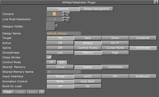
Properties
General
-
Camera: Defines working camera to accept screen input (which is useful in a scene with layers where more than one camera is used).
-
Line Pixel Resolution: Defines the required resolution of line during drawing, such that for example if resolution of 5 is set strokes less than five pixel size will be disregarded.
-
Designs Holder: Container beneath which the required design will be searched.
-
Design Name: A couple of designs may be implemented in the scene and here the desired one for current use will be set. If the required design does not exist, the first one found will be used.
-
Target: Defines where to build line strokes. If the Container option is used the desired container should be specified in "Target Container" section.
-
Active: Defines when the plugin will be active. It may be switched off, active always or only be activated while pressing ’p’ button on the keyboard. This is useful when other interactive capabilities are used in the scene (for example interactive navigation) and a care should be taken in order not to interfere these modes.
-
Spline: By choosing one of these options the final result will be smoothed for more pleasant look. The three spline types define three different methods for smoothing.
-
Control Points: Uses a spline that paths between the points of the original curve. This will result in the smooth nice curve but may be not accurate enough since the line doesn’t actually path through original route but may deviate from it.
-
Curve Points: Makes the spline path through points of interest of the original curves, but this method may also result in some artifacts causing the route to deform between points of interest, and that is due to a constraint that curve must be smooth.
-
Combined: Is a kind of compromise between Control and Curve points (see Examples)
-
-
Smoothness: If spline is used in order to obtain smoothed result the smoothness defines the threshold for such operation. The higher the threshold the softer the curve will be (see the examples at the end of this section).
-
Close Stroke: If enabled strokes will be automatically closed.
-
Control mode: While enabled evokes a shared memory mechanism to send and receive strokes to and from other 3D Map Telestrator plugins.
-
Shared Memory: defines type of shared memory:
-
Global: Shared within the region of computer.
-
Scene: Shared within the region of current scene only.
-
Distributed: Shared between all the scenes and computers in the network.
-
-
Shared Memory Name: Defines the name for connection, such that only 3DMapTelestrators with the same name will share data between them.
-
Input Interface: Selects interface type for line creation. See further remarks about "PPI" and "Multitouch" use.
-
Animation Control: When enabled runs animation that is located on design container after line is created (mouse button released).
-
Build On Load: Determines whether or not the lines created when the scene was saved, will be built when the scene is loaded.
-
Clear/Undo/Redo: Enables you to undo and redo last strokes or clear the whole drawing instead.
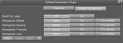
Shape Recognition
-
Build on Load: Determines whether or not the lines created when the scene was saved, will be built when the scene is loaded.
-
Recognize Ellipse, Square, Triangle and Line: Recognizes four shapes: ellipse (including circle), square, triangle and line. When the plugin recognizes a shape it rebuilds it to be of ideal shape (i.e. a hand-drawn circle will be replaced by a perfect circle of the same size). The Try Harder option means that there will be more probability to recognize the requested shape (for example the circle may be less ideal and still be recognized) running the risk that it might replace shapes that are not e.g. circles. When Try Harder is enabled only one shape can be recognized as opposed to the Try option which enables the plugin to recognize multiple shapes simultaneously.
Examples
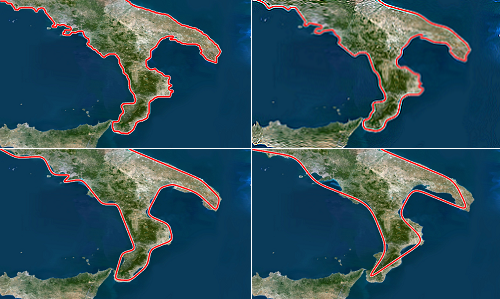
Influence of the curves parameter set to original, control points, curve points and combined:
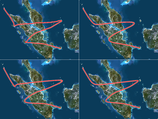
Influence of the curves parameter set to original, control points, curve points and combined:
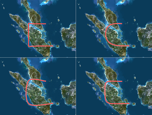
Influence of the smoothness parameter set to original, low, medium and high:
Creating a 3D Map Telestrator Scene
To create a 3D map telestrator scene
-
Prepare a blank workspace for the new scene, go to Geom Plugins -> Maps and drag an Atlas plugin to the scene
-
Open the Atlas plugin’s editor, and in under Data Source switch to CMR (Curious Multi Resolution), and in the CMR File locator locate the CMR with the desired map
-
This will create a map to draw on
-
If you have an Internet connection and license for Microsoft Bing maps you will see the world map as soon as you drop Atlas and there will be no need to load CMR
-
-
Go to Container Plugins -> Maps and drop the Navigator plugin onto the same container as the Atlas plugin
-
Remember to enable interactivity by pressing the E button (to the left of the scene editor).
-
Now navigation through the map is possible by pressing i button and using mouse. If the map suddenly disappeared after dropping Navigator plugin just click the Center Map button on the bottom of it.
-
-
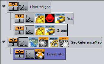
Add a container above the one just prepared and name it LineDesigns
-
Add a new container as a child of LineDesigns and name it Red
-
Add the 3D Line plugin to the Red container
-
Open the 3D Line plugin’s editor and set the Width parameter to Fixed (Pixels)
-
Set the Width’s sliding parameter to 4
-
Switch to the Outline option on the topmost radio button row and set Outline to On and give it a width of 50 (Outline Width (%) parameter)
-
Add material to the container and make it to be red color. This will create the first design for the line.
-
Add another container beneath the Red container and name it Green
-
Add the 3D Line plugin to the Green container
-
Open the 3D Line plugin’s editor and set the Width parameter to Fixed (Pixels)
-
Add a material with a green color to the container
-
This defines the second design for the line named "Green".
-
-
Add a new container as a child of the Atlas container and name it Telestrator and add the 3D Map Telestrator plugin to it
-
Open the 3D Map Telestrator plugin’s editor and drag the LineDesigns container onto the Designs Holder placeholder
-
Set the Design Name parameter to Red (in order to choose red design)
-
Set the Active parameter to the On P position
-
Set Shared Memory parameter to Distributed
-
Save the scene
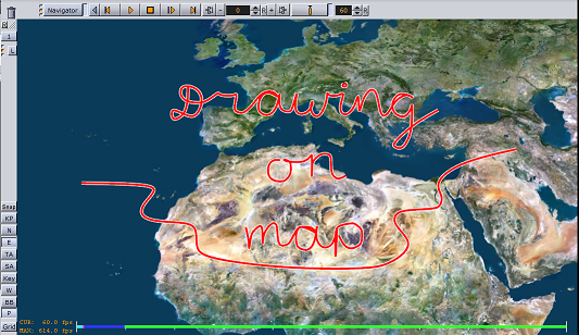
Now you should be able to draw on the map by pressing the P key on the keyboard and while holding the left mouse button down. Moreover, if you open the same scene on another computer in the network you should see the same drawings appearing on it too.
Non Geo-Reference Telestration
In the procedure on how To create a 3D map telestrator scene the drawing was done on the map, i.e. the path has geographic coordinates and as such it will be placed on the same geographical route when it will be sent to other computers (by using the Shared Memory Mechanism). The other map in the other scene may have different style and projection. It may also have globe geometry, and the path will still be geographically correct.
However, there is an option to use 3D Map Telestrator without map and geographic coordinates. In order to use this option two conditions must be met:
-
The plugin must not be located under geo-reference (in the example scene the Atlas was used as geo-reference), and
-
The flat geometry about to be drawn on must be placed on the same container with 3D Map Telestrator plugin.
Shared Memory Mechanism

As explained in the 3D Map Telestrator Properties section, the plugin uses a shared memory mechanism in order to send and receive strokes to and from other 3D Map Telestrator plugins.
In order for two plugins to interconnect they should have the same name for the shared memory data they are "listening" to. The given name should have a prefix of "Telestrator_", such that when a user enters the name "alpha" for the group of 3D Map Telestrator plugins, the actual name of the shared memory parameter will be: "Telestrator_alpha".
The format of data consists of a unique id that each stroke receives, name of required design and data path that comes as a sequence of pairs of numbers representing longitude and latitude (when non-geo-reference mode is used the flat geometry’s bounding box is treated as if having the lat/long coordinates of full world). All components of the data including design name and unique id are separated by commas.
Using Multitouch Interface
This interface uses touch screen of Multitouch type. In order for the plugin to receive information from the screen the Input Interface button should be switched to Multitouch mode and a container with the plugin should contain a geometry. Screen touches outside of this geometry will be disregarded. So, if the plugin is used in a non-georeference mode there is no problem since it already contains geometry you are drawing on. If it is used in a georeference mode the best practice would be to place the 3D Map Telestrator plugin on the container with the map.
Using Perceptive Pixel Interface
In a case of using a Perceptive Pixel Interface (PPI) screen the setup requires a couple of additional things to be done. A special plugin named Mt2dControl, that is a part of the PPI plugin package, will accept and process the inputs from the touch screen and the processed data will be sent to the 3D Map Telestrator plugin through a shared memory mechanism.
Continuing the procedure above on how To create a 3D map telestrator scene, you can add multi-touch capabilities to your graphics scene. Hence, the below procedure and example scene tree expands the aforementioned procedure.
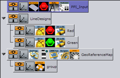
-
Open the 3D Map Telestrator plugin editor and set Input Interface to PPI (see Properties) and chose a name for a shared memory connection with the PPI interface (i.e. a PPI variable name). Note that this must differ from shared memory connections with other 3D Map Telestrator plugins
-
Add the container somewhere in the scene which will not be a part of any hierarchy
-
Add a rectangle to the container and scale it to the maximum possible size
-
Add a Mute plugin on the container in order to avoid rendering it
-
Add a Multi-touch 2D control (Mt2dControl) plugin on the container
-
Open the Mt2dControl plugin editor and set the following parameters:
-
Lock Rotation to On
-
Lock Scale to On
-
Shared Memory to On
-
Shared Memory Type to Scene
-
Shared Memory Prefix should be the same as the PPI variable name in the 3DMapTelestrator plugin
-
Hit Coordinate Type to World
-
-
Save the scene
-
Now you should be able to draw lines by touching the screen
-
See Also
Brush Design Using 3D Line
The 3D Line plugin is used by the 3D Map Telestrator to visualize the strokes. The desired look of the line is set by various parameters in the design (inside the 3D Line plugin) and it is therefore important to understand these parameters in order to get the desired look and behavior for the line.
The following are the most important parameters:
Width
The options for the Width tab defines the width behavior of the line. Three options may be used to define width behavior:
-
Fixed (pixels): Defines constant width of line measured in pixels
-
Scaling: line width may vary according to zoom and the minimum-maximum parameters could be set
-
Fixed (mm): Sets a fixed width in geographic units
-
Fade Edge (%): Applies a fade effect to the side-edges
Outline
By using these options an outline of arbitrary width, fade amount and color can be set to a line.
Effect
Note that by default when a line comes to a 3D Map Telestrator plugin it plays an animation running from single point to a full path. The attributes of such an animation can be set beneath this tab. The length of animation in time is controlled by the Animation Length parameter and if it is set to ’0’ no animation will be played at all. Moreover, a nice fade effect to a running edge of the line could be set by the Fade parameter.
Advanced
A couple of options are available for this tab, the most important of which are:
-
Cap edges: Defines shape for the beginning and end edge of the curve
-
Height Offset: Defines an offset line from surface it is put on
-
Update Texture Mapping: Note that a texture may be applied to a line. During zooms, line width is updated according to the setting we made in Width tab, while line length remains unchanged, thus texture mapped on the line may deform. In order to keep same aspect ratio for the texture this option must be enabled.