Viz World User Guide
Version 17.0 | Published January 24, 2018 ©
3D Border Control
![]()
The plugin can be found in the folder: Viz Artist 3: Built Ins -> Geom Plugins -> Maps-Adv.
The 3DBorderControl plugin is used to control the attributes of a group of 3DBorder objects. The plugin controls the applied material, border width, edge softness and visibility.
Note: The 3DBorderControl plugin does not build the 3DBorder objects. The controlled 3DBorder objects should be built before the 3DBorderControl is used.
The 3DBorderControl plugin has two modes:
Control
-
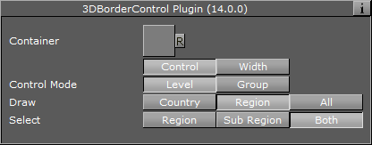
Container: Placeholder for the top container of the 3DBorder objects. All controlled 3DBorder objects must reside directly under the top container. Any lower level containers will not be effected.
-
Control Mode: Defines how the objects will be grouped when controlled by the 3DBorderContol plugin. When set to Level, the 3DBorder objects will be grouped by their data type (that is country, region and sub-region).
Control Mode Level

-
Draw: Defines what data types will be drawn. 3DBorder objects with other data types will not be switched off:
-
Country: Shows 3DBorder objects displaying country borders only.
-
Region: Shows 3DBorder objects displaying region and sub region borders only, according to the user selection. Available options are; Region (draws region borders), Sub-Region (draws sub-region borders) and Both (draws both region and sub-region borders).
-
All: Draws all border types (that is country, region and sub-region).
-
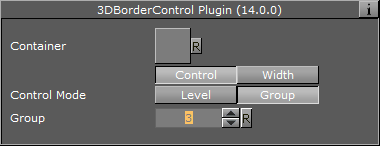
Control Mode Group

-
Group: Defines the group number that will be visible and controlled by the 3DBorderControl plugin. Groups are defined in the 3D Border plugin in the Advanced tab’s Set Groups parameter.
Width
![]()
-
Fixed (Pixels): Uses a fixed width when drawing the line. This parameter will cause the line to maintain the same width regardless of camera position/distance. Available parameters are Width and Fade Edge.
-
Width (Pixels): Sets the line width in pixels.
-
Fade Edge (%): Sets the percentage of softness added to the edges of the line. When set to 0% the line edges will be sharp and when set to 100% the edges will be soft.
-
-
Scaling: When selected, line width will vary according to the camera distance from the map. Available parameters that allow the user to set the line attributes are Width, Minimum Width, Maximum Width, Minimum Draw Width and Fade Edge.
-
Width (Kilometers): Sets the line width in meters on the map. The closer the camera to the map, the wider the line will be drawn.
-
Minimum Width (Pixels): Sets the minimal line width in pixels. If the calculated line width (according to the Width parameter) is smaller than the Minimum Width value, then the Minimum Width value will be used.
-
Maximum Width (Pixels): Sets the maximal line width in pixels. This value will be used when the camera distance is small and the line width should have been larger than the Maximum Width value (in pixels).
-
Minimum Draw Width (Pixels): Sets the minimal line width in pixels. If the calculated line width (according to the Width parameter) is smaller than the Minimum Draw Width value, and larger than the Minimum Width parameter, then the line will not be drawn.
-
Fade Edge (%): Sets the percentage of softness added to the edges of the line. When set to 0% the line edges will be sharp and when set to 100% the edges will be soft.
-
-
Fixed (Mm): Uses a fixed width, in Viz units, when drawing the line. This parameter will cause the line to maintain the same width regardless of camera position/distance. Available parameters are Width and Fade Edge.
-
Width: Sets the line width in pixels.
-
Fade Edge (%): Sets the percentage of softness added to the edges of the line. When set to 0% the line edges will be sharp and when set to 100% the edges will be soft.
-