Viz Vectar User Guide
Version 1.0 | Published May 07, 2020 ©
Output Configuration

Roll the mouse pointer over the Program monitor to reveal a Configure button at right in the titlebar below the display. Click it to open the Output Configuration panel.
Tip: As for other viewports, alternatively two finger tap on a touchscreen or, if Click Viewports to Show on PGM is disabled in the Options menu, double-click the mouse on the viewport to open this panel.
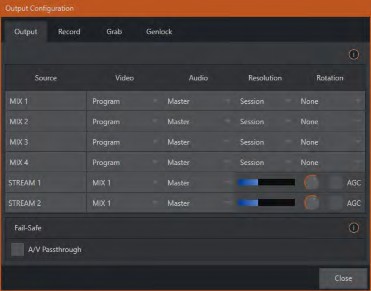
The Output tab in this panel contains controls governing the system’s primary outputs.
Output Tab
We discussed Primary and Secondary outputs in Configuring A/V Output. The first four entries in this panel are primary outputs; typically, these are also mixed outputs, hence their default labels – MIX 1, 2, etc. These video sources are sent to the corresponding SDI output connectors (when provided), and also as NDI (Network Device Interface) outputs.
Video
The primary outputs support the largest number of optional video sources and, uniquely, can follow a delegated M/E, or a Switcher color group. All other outputs can be assigned to follow a primary output or show another designated Switcher source (excluding M/Es).
Audio
In similar fashion, you can choose which audio source accompanies any of the primary outputs. Choose any individual audio mixer input, or any of the mixed audio outputs, Master or Aux (audio mix options vary by model).
Resolution
The Resolution menu allows you to choose the video format for each output. Select the video format for downstream devices you intend to connect to the corresponding output here. The formats available are drawn from the list below, according to whether the session is in PAL or NTSC mode:
-
2160p
-
1080i or 1080p – depending on the session format
-
720p
-
480p – progressive standard definition NTSC sessions only
-
480i (4:3) –interlaced standard definition NTSC sessions only
-
480i (16:9) –interlaced standard definition interlaced NTSC sessions only
-
576p – progressive standard definition PAL sessions
-
576i (4:3) –interlaced standard definition PAL sessions
-
576i (16:9) – interlaced standard definition PAL sessions
Note: Outut 1 always transmits video in session format, thus shows a Resolution display only.
Generally, source formats that are inconsistent with the current output resolution setting are automatically conformed when possible. In some cases, such as non-standard format sources, the output format may be modified to provide a suitable display. That said, it’s best to avoid non-standard sources if possible.
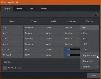
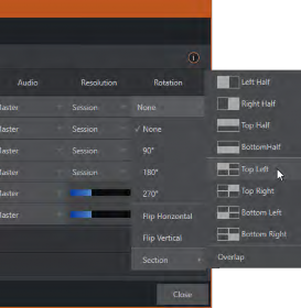
Rotation
Video Mix also support independent rotation and flip controls, as well as Section options.
Stream
The Stream controls in the Output tab let you independently assign any of the primary mixes to one or two streaming encoders. Likewise, for models with multiple audio busses, you can send audio from the Master audio mix or any of the Aux busses to either streaming encoder.
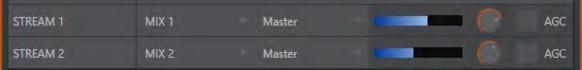
The audio controls also include individual VU meters, Gain knobs, and an AGC (Automatic Gain Control) option. These allow you to modulate audio for the streams separately from your primary audio outputs.
Tip: Streaming ouput is always de-interlaced.
Streaming Output involves more options, too, since there are so many different ways to stream. In this panel, configure the audio and video sources sent to the streaming output. All other options and settings relevant to streaming are discussed in Stream/Encode.
Failsafe
Vizrt’s multi-tiered Always on Air hardware and software failsafe systems provide confidence that, short of a complete power failure, the show goes on. Video passthrough ensures that as long there is power, audio and video from hardware Input 4 is routed to Output 1 in case of a catastrophic software condition. If at all possible, streaming output and recording also continue even if all else fails.
In some studio settings, however, more elaborate hardware failsafe systems may be in use. Typically, such systems take over broadcast duties whenever the output signal fails. In this sort of pipeline, the native failsafe video passthrough mechanism can actually prevent the external system from engaging.
For this reason, a Failsafe control group has been added to the Output tab. This lets you disable the A/V passthrough when necessary.
Note: A/V passthrough is off by default and must be deliberately enabled to function.
Tip: Only use fail-safe when a stable video source is connected to video Input 4.
Record and Grab Tabs
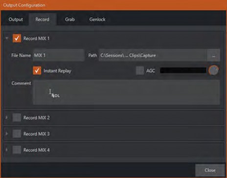
Each MIX output source has corresponding Record and Grab control groups to provide settings and options for capture. These important capabilities are discussed in full in Record, Grab and Replay. The controls shown in are detailed in Record (Grab is virtually identical, but for the lack of an Instant Replay feature).
Genlock Tab
The Genlock feature allows your Vizrt system to lock video output to a reference video signal supplied to its Genlock input connector. This synchronizes system video output to external equipment locked to the same reference. Genlocking is not a requirement, but it is very beneficial, and you should definitely use it if you have the capability. Miniscule local timing differences between these may force tiny delays during switching operations, which can contribute to throughput latency. Thus, serving i) the Genlock input and ii) other video devices in the chain with a single reference is the best approach.
You could think of it this way:
-
Genlocking your cameras has the effect of locking their output together, ensuring optimal synchronization for live switching. This may result in throughput latency benefits.
Tip: The term genlock refers to generator locking. Professional video devices often provide a genlock input, which allows an external reference signal (often referred to as house sync) to control its video timing. The output of video devices connected in this manner is synchronized to the reference signal, and they are referred to as genlocked.
-
Supplying the same sync source to the Genlock input ensures a match between the system’s video output and any downstream video devices required to handle both it and other (genlocked) sources.
Note: Digital audio is less tolerant in certain respects than analog. Some devices require SDI sources to be genlocked when mixing digital audio (whether for recording or live production).
Vizrt systems, however, include dynamic audio re-sampling for each input. Genlocking SDI audio/video sources is not a requirement. Still, genlocking sources and other production devices to a single house reference signal, or genlocking the cameras directly to the Vizrt live production system’s output is encouraged (to genlock cameras, see your camera manual).
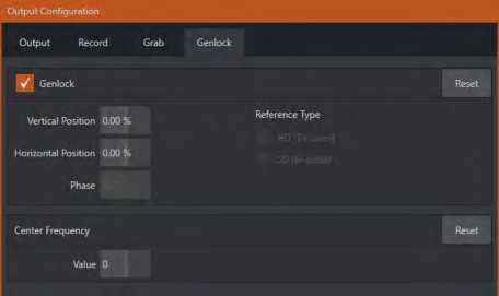
Genlock settings are hosted in a tab by the same name in the Output Configuration panel.
Vertical Position, Horizontal Position and Phase
Locking all devices to house sync is important, but this alone does not actually ensure a perfect downstream match. Consider an army marching along: each step the soldiers take occurs at precisely the same moment, so we could say their timing is synchronized. Even so – problems result if one soldier leads with the left foot while everyone else is on the right. Or perhaps everyone is evenly spaced and perfectly aligned but for one misfit who tailgates the soldier ahead of him and keeps stepping on his heels.
This is essentially why adjustable settings exist in the Genlock panel. The Horizontal and Vertical Position settings pin the image in the proper space in the frame, and in doing so could be likened to making sure each marching soldier is in position relative to his fellows (as viewed from above).
The Phase setting ensures proper color alignment, corresponding to making sure everyone is on the left or right foot at the same time.
Together, the Vert Position, Horiz Position and Phase settings let you tweak synchronization to arrive at an optimum match between devices. Typically, these settings are fine-tuned with the aid of a downstream vectorscope and waveform monitor. (A discussion of these adjustments goes beyond the scope of this manual, but a quick online search for the keywords “genlock” and “adjust” turns up a number of excellent references).
Reference Type
The bi-level reference signal long used for standard definition television is often used for genlocking both SD and HD installations. However, the HD (Tri-level) reference sources are also supported by the Reference Type settings option.
Note: Reference Type options do not appear for SD sessions. Also note that 1080/59.94p Tri-level genlock signals are not supported.
Center Frequency
This setting is applied when a genlock reference signal is not in use. To adjust the setting, supply color bars to an input and pass video output to a downstream vectorscope. The vectorscope display is completely stable when Center Frequency is properly adjusted.
See Also