Viz Vectar User Guide
Version 1.0 | Published May 07, 2020 ©
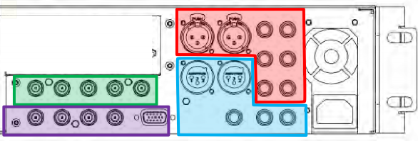
Input Connections
Connect A/V Sources
-
Analog audio inputs: 1-4.
-
Analog audio outputs: 1(Master) & 2 (AUX 1), and Phones jack.
-
SDI Video Inputs 1-4 and Genlock input.
-
SDI Video Outputs 1-4 and Tally connector.
Note: Connect any local SDI video sources to one of the four BNC connectors in the SDI IN section. Hardware details as depicted are subject to change without prior notice.
Connecting a Control Surface
Please refer to Connection and Configuration for a discussion of connecting and configuring control surfaces.
Connecting a Video Router
With the appropriate software installed, your system can control and access output from router models supporting the popular Grass Valley® Native Protocol, as well as Black Magic Design® Video Hub routers.
The implementation offers a number of configuration options; a basic setup would be as follows:
Connect the router to the system by Ethernet cable, and then connect one (or more) of the router’s video outputs to SDI inputs with matching numbers, using suitable video cables (For example, by default router output number 3 would be connected to Input 3 for control communication between the devices to be properly linked).
-
Click the Shutdown icon on the Home page (Launch Screen) and click the Administrator Mode at right.
-
In the Administrator Mode panel, click Exit to Windows.
-
Navigate to the appropriate folder below by model:
-
C:\ProgramData\vizrt\Vectar\Configuration
-
-
And open the file named router_setup.xml by double-clicking it (it opens in Notepad). This file is where you add the routers you wish to connect. Each router is identified by an entry you insert between the starting and closing “config” tags, as explained in the file comments.
Example entry:
<grassvalley ip="10.28.1.128" port="12345" name="AJA KUMO"/>
-
Save the file after editing and re-launch the system.
Note: The system communicates with routers using individual IP address and port numbers, allowing multiple routers to be connected simultaneously. File comments explain how you can bypass the default 1:1 mapping of router outputs to inputs when required and prevent accidental changes to inputs that are displayed on Program output, along with other extended configuration options. If you assign names to router inputs or outputs in this file, make sure the names for each are unique.
Some routers allow each router input to be provided with a unique name. In such a case, Vectar may be able to access that name and use it for Switcher buttons as appropriate.
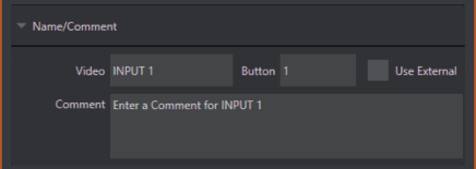
To enable this behavior, check the Use External (name) switch in the Input Configuration panel. See Input Configuration for more detail.
Black Magic Design® Auto-Detection
For backwards compatibility reasons, these routers are auto-detected by default. (Black Magic® routers may use a USB control connection, rather than a network connection. The router’s firmware should be up to date. If detection fails, please contact BMD support for assistance.)
You can, if you wish, disable auto detection by editing the XML configuration file discussed above. (You might do this to avail yourself of the extended configuration options that are provided by doing so.) To do this, simply add the line below to the <config> section of the file.
<blackmagic_config discovery="false"/>