Viz Vectar Plus User Guide
Version 1.3 | Published November 18, 2022 ©
Switcher Transitions and Overlay
Live Desktop features replicate traditional hardware video switcher controls. For example, the Live Desktop includes powerful transition controls, downstream overlay channels, interactive layer monitors, and powerful automation features.
The middle of the Live Desktop (between the monitoring section and the tabbed modules) is the switcher with controls and configurations that include Layer controls for main and DSK (Downstream Keyer) Transition controls.
This section covers the following topics and procedures:
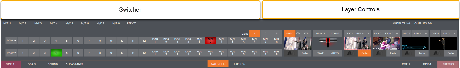
Switcher Modes
Viz Vectar Plus supports two Switcher modes. Select one that best suits your production.
![]()
-
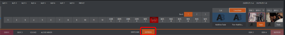
To select switch operating mode, click either the SWITCHER or EXPRESS tab provided at right in the horizontal bar immediately above the Switcher pane.
SWITCHER
This is the standard setting, providing control over your main Program video output using the familiar Program/Preview row method.
EXPRESS
For less complex productions, Express mode simplifies tasks, offering a one-button operating mode. Can be useful where volunteers or less experienced operators are working with the production.
Tip: Touchscreens are supported. Tap a source’s viewport to instantly send that input to Program output using any current background transition.
Switcher Row Banks
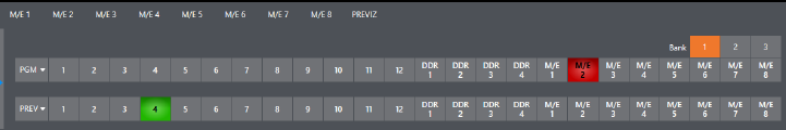
In standard Switcher mode, two Switcher rows labeled PGM (Program) and PREV (Preview) are shown. Clicking a button in the Program or Preview row selects the active video source for that bus (note that Audio sources can optionally be affected by Switcher activity).
Program and Preview rows represent all available video sources in banks of buttons. The number of banks vary according to the number of supported sources.
-
Bank 1 is shown by default.
-
Hold down ALT on the keyboard to reveal Bank 2.
-
Releasing ALT, Bank 1 is re-displayed.
-
Press ALT + CTRL to momentarily display Bank 3 (when supported).
-
It’s possible to latch banks, either by clicking Bank buttons on the screen, or by pressing TAB to cycle the currently displayed bank.
Tip: The standard Switcher (and M/Es with transitions assigned) show selection hint tags beneath their rows when the selected source is in another bank. Click a tag to jump to the bank the source is hosted in.
Program/Review Rows
The video source selections in the Switcher rows include all external inputs, including video router sources, internal sources (Media Players and Buffers), and the output from all M/Es.
|
|
The PGM (Program) row selection determines the dominant video stream of the Background (BKGD) video layer – that is the rear-most layer of the composition sent to Program output. Other sources may be mixed above the Background layer at times as you apply LiveMatte, or as portions of an incoming Preview row video source appear during a transition. |
|
|
The Preview row appears in standard Switcher mode. Selections determine which source is queued up for display in the Background layer by a subsequent (BKGD) Take or Transition operation. |
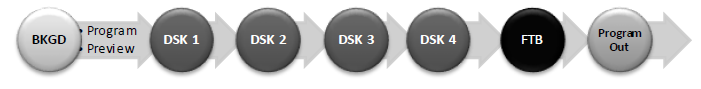
Background and DSK Layers
The concept of video layers is central to understanding how the Switcher, M/E and Transition controls relate to one another, and how they combine to form the video seen on Program output.
-
The Background layer (often shortened to BKGD) is always the base for the video composition displayed on Program output.
-
DSK (Down Stream Keyer, or overlay) layers may appear above (in front of) the Background.
DSK layers are typically used for overlaying objects like graphics or titles, although they may serve other purposes as well. In addition to BKGD, up to five additional primary layers can contribute to the final Program output:
-
Overlay layers (DSKs) are composed above the BKGD layer on output. DSK 2 appears in front of DSK 1 on Program Output (closest to the viewer) and so on, in numerical order.
-
FTB (Fade to Black) constitutes a final overlay layer – one that obscures all other layers when applied.
The BKGD layer is often a composite of sub-layers:
-
It may include mixed video from both the Program or Preview rows.
-
Selecting an M/E as source on Program or Preview can add many sub-layers to the BKGD composition, including the M/E’s primary Inputs and dedicated KEY layers.
KEY layers are similar to DSK layers but, being upstream of the main Switcher, appear composed in the background layer.
Note: Multiple M/Es can be in use, so the BKGD layer can comprise high numbers of sub-layers.
Selecting Sources
-
Standard Switcher mode: Video sources for PGM (Program) and PVW (Preview) rows are selected individually by pressing buttons on those rows.
-
Express mode: By contrast, selecting a button on the single row in Express mode first places the designated source on the (unseen) Preview bus, then immediately switches it to Program output.
-
For DSK/Key layers, source selection is made using a drop-down menu above the integrated viewport located in the DSK/Key control group.
Hint: Right-click input buttons to select sources from video routers (see Configuring Routers).
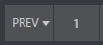
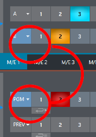
Linking Switcher Rows
It can be useful to link two (or more) Switcher or M/E source rows together, so they operate synchronously.
-
Program and Preview rows and M/E source rows all show a Triangle beside the row label at left.
Click it to open a menu for setting up linking.
Rows assigned to the same color groups are linked. A selection made in any linked row updates the selection of all other rows in the same color group to match.
The screenshot shows the Input A row for an M/E linked to the PGM row of the main Switcher.
-
The Ungroup menu item removes the current row from a group, while Clear this group removes all rows from the current group.
Transitions and Effects
This section presents layout and use of the Transition controls.
See also section Background and DSK Layers.
Standard Switcher Mode
With the Switcher in its Standard mode, multiple operations are available.
At left in this group are the main Transition controls, including the T-bar. The control groups right of the T-Bar provide configuration and control options for the individual DSK layers.
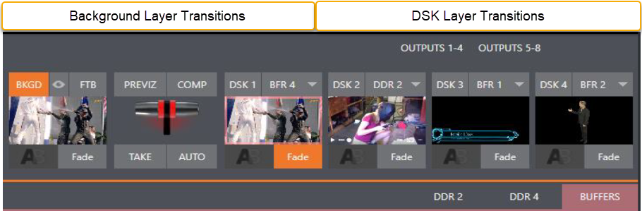
DSK Controls
Each DSK layer has a live video viewport showing the current source assigned to it (using the menu at right above the viewport) and its own transition effect. Click the transition icon at lower left below the viewport to reveal a palette of different transition presets provided for quick selection. Click an entry in the palette to select it, or move the mouse pointer to the + sign that pops up for each icon and click to open the Custom Media Browser.
Tip: The frequently-used Cut and Fade effects always available in the transition palette. As these cannot be replaced, no + sign appears for these icons.
In the Media Browser, you can choose from hundreds of transition effects. The selected effect replaces the current one in the palette. To display or hide the DSK video layer over the BKGD layer on Program output using the currently selected effect, click (or tap) the viewport or the effect name label just below.
Tip: You can halt an unfinished effect by clicking again during the transition. Click it again to continue performing the effect.
Transition Delegates
You can also control transition progress using the Switcher’s T-Bar control, at left. The T-Bar operates on all delegated video layers. To delegate a DSK, click its label at upper left () to turn it blue. Clicking it a second time un-delegates the layer. The T-Bar acts on all delegated layers, including the Background video layer. For example, if DSK 1 is visible, but DSK 2 is not, when both DSKs and BKGD are delegated performing a T-Bar (or BKGD AUTO) operation reverses the visibility of the two DSKs on Program output when the BKGD transition occurs.
Transition Timing
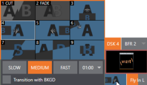
Per transition timing is set and stored in the effect palette, using the numeric duration control beside the effect icon. Select transition speeds using the menu below the Transition Palette. You can also drag the mouse pointer over the numeric display to set a custom time, or click it to enable keyboard entry of the effect duration.
Tip: The direction of Transitions applied as DSK (and M/E KEY) layer effects automatically alternates. If the first click displays the layer using an effect, the next click removes it using the reverse effect.
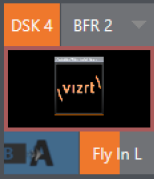
DSK Source Configuration
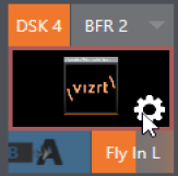
Many more configuration options are available for DSKs (and their siblings, M/E key layers, too). To access these settings and features, roll the mouse pointer over the DSK viewport, and click the configuration (gear) gadget that appears at lower right.
Tip: Touchscreen users can two-finger tap the viewport to open the Configuration panel.
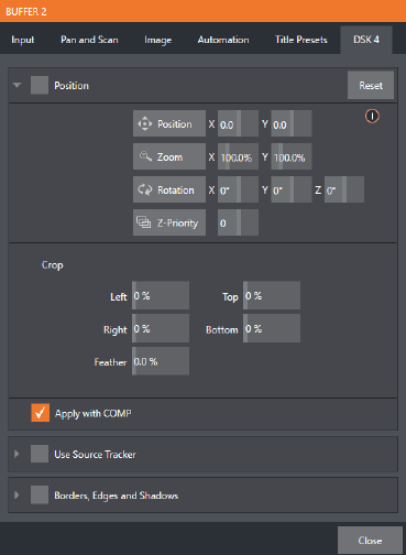
Doing so opens the Input Configuration panel for the source assigned to the DSK, but with the addition of a supplemental tab labeled DSK (1-4). The control groups in this new tab expand to reveal Position, Use Source Tracker and Borders, Edges and Shadows settings.
Position and Crop
-
The Position control group includes Position, Zoom, Rotation, and Priority. Position settings can be toggled on and off together using the switch provided in the group header.
-
Click and drag on the Position button (diamond) to relocate the DSK layer vertically or horizontally within the frame.
-
Drag left or right on either of the two nearby numeric controls to adjust a single axis only. Dragging the cursor on the Zoom button (magnifying glass) affects the apparent size of the overlay.
-
If you drag just one of the associated numeric gadgets you can adjust just one dimension of the corresponding DSK layer – width or height.
-
In similar fashion, drag the pointer over the Rotation button with the left mouse button depressed to turn the overlay source on three axes as follows:
-
Drag left/right to rotate the source about the Y (vertical) axis.
-
Drag up/down to rotate about the X (horizontal) axis.
-
Drag while holding ALT down to rotate about the Z axis.
-
Drag on a single numeric slider, or hold down CTRL to constrain rotation to one axis.
-
Tip: If you click a numeric field (or right-click it), you can type a value into the gadget using the keyboard; press ENTER to complete the editing action, or ESC to cancel it).
The Crop DSK/KEY controls in this group are similar to those found in the Input tab, as discussed in Input Configuration. However, these settings are applied to the DSK/KEY layer, without any impact on the source itself as it may be displayed elsewhere in the Switcher.
Info: DSK and KEY layers automatically appear on the Preview and (M/E Preview) monitors when the Position panel is open (regardless of layer display options). This allows you to modify a layer’s position without the result being inadvertently shown on output.
Z-Priority
Normally, KEY and DSK layers appear in numeric order from back (furthest from the viewer) to front. This if DSK 1 and DSK 2 are both displayed and occupy the same position in the frame, the content in DSK 2 occludes DSK 1.
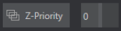
The Z-Priority setting in DSK and KEY layer positioning panels allows you to revise the default layer order on a selective basis. This feature was specially implemented to provide additional flexibility for use with the COMPS feature.
For example, imagine an M/E set up with 4 KEYs supplying a quad-box setup for four remote interviewees over a background supplied by the M/E. You might want to use Comps to zoom the top-left input up to fill the screen while the moderator chats with that person. Normally, KEYs 1-3 would always appear behind KEY 4 – not what you want at all. Z-Priority lets you move any KEY to the front (and the setting is stored in your Comps).
The range of Z-Priority settings runs from -10 to +10, with a default 0. A layer with a higher index is shown in front of those with lower indices. When two layers have the same layer priority, they are rendered in their natural (DSK/KEY layer) order.
Apply with Comp
Comps are a type of preset that stores complete Switcher or M/E setups.
By default, the settings stored in a Comp include the Position, Crop and visibility state for each DSK or KEY layer. Disable the Apply with Comp feature if you want to exclude a given DSK/KEY channel from Comp control, handling it manually instead.
Tip: Ensure that a station ID bug shown over output is not accidentally removed by application of a Comp.
See section Comp system.
Use Source Tracker
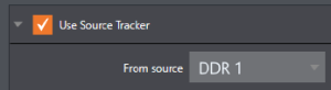
Use Source Tracker lets you assign motion data output from the Tracker for any video source to modify the position of the current DSK or KEY layer by selecting it in this menu.
Position settings enabled in the DSK/KEY tab continue in force but are applied relative to Tracker output. For example, X and Y Position settings entered in the upper part of the panel result in an offset from the co-ordinates supplied by the Tracker.
See section Input Configuration.
Borders, Edges and Shadows
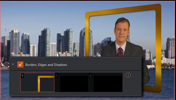
The Borders, Edges and Shadows group also provides each DSK, KEY and M/E layer with three quick access border preset slots.
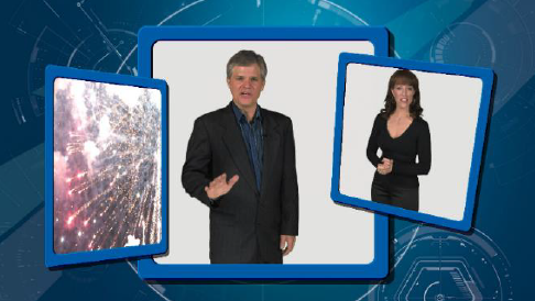
Tip: Since these are per-layer Position effects and can be controlled – even animated – by Comps, you can use the Borders feature to create custom multi-box compositions in M/Es.
These powerful effects can include full color overlays, backgrounds, matte layers for keyhole effects, and shadows.
-
You can freely scale, position and rotate various Switcher sources, add custom borders, overlays, shadows, and so-on, over custom backgrounds.
-
In addition to hundreds of supplied borders, you can easily create elaborate custom effects using Adobe Photoshop™.
-
Define a Photoshop™ format file with three (rasterized) layers.
-
The uppermost layer contains foreground elements (such as a bezel).
-
The next layer is treated as a mask based on opacity and defines the part of the source image that appear in the result.
-
The bottom layer supplies a background to appear behind transparent parts of the source (as, for example, when LiveMatte is applied to a source).
-
A template PSD file is supplied to assist you to do this. The multi-layer Photoshop™ file is in the Borders folder at C:\ProgramData\vizrt\Effects\Borders.
Tip: Since the opacity of the mask layer can vary between fully opaque and fully transparent, you can easily prepare soft-edged effects such as vignettes. Also, as foreground and background layers can optionally be empty, a simple opaque shape in the mask layer can serve a variety of imaginative purposes.
Transparency
Sources assigned to DSKs are often partially transparent. This might be because they are drawn from a Media Player (DDR) file that includes an embedded alpha channel, or because LiveMatte or Crop options are enabled for the source, or perhaps because a Network source includes an alpha channel, or even all of these factors operating together.
In all of these cases, DSK layers automatically respect transparency when supplied by the source. The BKGD layer and all visible content in lower-numbered DSKs appear through or around sources with transparency as appropriate.
Important: It’s best to use files with straight (non-premultiplied) alpha channels for media players. Premultiplied files generally do not yield correct results when overlaid on other imagery.

DSK layers offer a lot of creative possibilities. For example, you can use DSK channels to display a permanent station ID bug, superimpose a company logo onto a title page, add a spinning globe animation playing in the DDR to a lower-third, frame a keyed source composed over a title, or set up other similar effects.
Background Controls
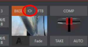
The QuickSelect button (marked with an Eye icon to associate it with visibility) is located in between BKGD and FTB.
-
Click to update the Switcher's T-Bar delegate and transition states so that the next TAKE or AUTO operation will remove all visible DSK or KEY layers from output.
(On supporting control surfaces, press ALT and BKGD to trigger the QuickSelect feature).
Background Transition Group
Transition controls in this section apply to the Background video layer only. In most respects, these tools are identical to the DSK transition controls discussed earlier, but there is one difference worth mentioning.
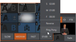
The Duration menu for the Background transition offers two items not included in the similar DSK/KEY controls:
-
Reverse: Configures the current transition to run in reverse direction the next time it is applied.
-
Ping Pong: Causes the direction of the transition to be automatically swapped after each time it is applied.
FTB
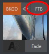
The acronym stands for Fade to Black. FTB offers a convenient method of doing what its name implies – fading Program output completely to black. It might help to think of FTB as a final video layer added above all others before Program output, completely obscuring everything below it.
As a memory aid, the FTB button pulses during operation. FTB’s fade duration is drawn from the BKGD transition setting.
Note: Hold down SHIFT while pressing the FTB button on a control surface to initiate an FTB operation. Hiding or displaying FTB triggers both Autoplay and Audio Follow Video when enabled for Media Players. It also fades Master Audio to mute when displayed, and back up again when hidden.
Take and Auto
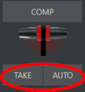
Clicking the Background layer’s Take button (keyboard shortcut ENTER) performs a straight cut for all video layers that are currently delegated. Likewise, if you press Auto (or the keyboard SPACEBAR), the transitions assigned to all delegated video layers are performed.
Tip: You can halt an Auto operation partway by clicking the button a second time during the transition. The operation is completed the next time you click the button.
T-bar
Enables manual transition between selected video layers. Pull it downward by dragging it with the mouse pointer. Drag it all the way to the bottom and release to complete a transition; the T-bar then pops back to the top.
Tip: When the T-bar is dragged part way, a partial transition occurs. With certain transitions this can be useful for split screen effects.
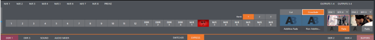
Express Mode Switcher
Express mode presents a simpler view of the Switcher, intended for less complex productions.
-
To open Express mode, click or tap the EXPRESS tab at right above the Switcher.
Background Transition
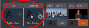
Note the quad-selector located between the single Switcher row, and the DSK controls at right. Cut and Crossfade mode buttons top this control group.
-
Click or tap either the Cut or Crossfade button to activate the corresponding Background transition.
Just below these you see two selectable transition controls. -
Tap or click these to activate the effect represented by the icon as the current Background transition instead.
-
To open a transition selector to choose a different transition for either of these slots, click the gear that appears at lower right when your mouse pointer is over the icon.
Tip: Although the gear is not visible in a touchscreen scenario, you can still tap the lower right corner of the icon to open the transition bin.
Switching
-
Selected the Background transition.
-
Click or tap the button for the source you wish to send to Program output.
There is no need to make a Preview row selection first, as you would need to do in the standard (two-row) Switcher. -
The Background transition you chose is applied to display the new source.
DSKs
The two DSK control groups at right work just like the Standard Mode Switcher, but it is particularly handy that you need to click or tap their viewport to show or hide the associated DSK layer.
Transitions with Animation Store Creator
You can also employ special transition effects called Animation Stores. A useful utility the Animation Store Creator is included in your Live production system.
-
These powerful effects normally include an embedded full color animated overlay, along with sounds for transitioning in and out (sounds are optional).
-
The audio level for Effects is controlled in the Audio Mixer tab below the Switcher.
-
Animation Store transitions are loaded into the Transition Palette in the same way as simpler transitions, using the Browse feature.
-
Some Animation Store transitions contain custom animation content you have to access to can only be modified with third party software.
To open the Animation Store Creator
-
From the Start-up screen, select Add-Ons > Animation Store Creator.
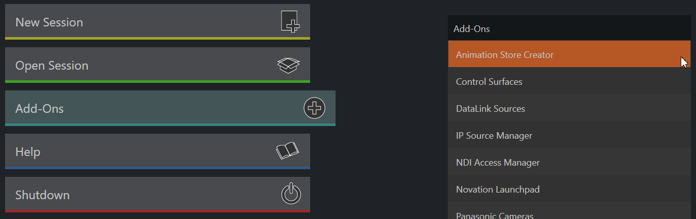
Note: The Animation Store Creator utility is described in its own manual, available at the Launch menu (Help > Add-Ons > Animation Store Creator) or at the Vizrt Documentation Center.
Comps
The COMP button, immediately above the T-Bar opens the Comp Bin, which provides powerful layer and effect control features.
-
Refer to section Comp Bin.
Comps are not MEMs
Note: It is important to distinguish Comps and Switcher MEMs.
-
The main difference is that MEMs retain (and apply) all settings in the Switcher, including source selection.
-
Moving the cursor to the left edge of the screen next to the Switcher or an M/E reveals a MEM bin with similar features.