Viz Vectar Plus User Guide
Version 1.3 | Published November 18, 2022 ©
Default Effects
In Effect mode an M/E may support up to four input layers. The M/E doesn’t transition between A and B in Effect mode. Instead, effects of various types are applied to the selected video inputs.
This section focuses on the Default group as examples.
Working with Default Effects
-
Click the + sign shown when you move the mouse to the effect icon located beside the effect duration.
This opens the Media Browser. -
Select the effect group labeled Default under the LiveSet location at left. With the exception of Advanced Tracking effects, these effects are straightforward compositing effects involving multiple video layers. Effect output (the background prior to KEY overlays) is the sum of all input layers.
If the source assigned to input A is fully opaque, any content in the layers below is hidden. When input A is at partially transparent, the source assigned to input B is blended into the M/E background layer, and so on.
Tip: Don’t overlook the fact that the input Position controls, including Borders, let you create very elaborate compositions even with simple compositing effects.
The output of active KEY layers is then added to the effect output before passing the combined result onward as the final M/E output.
Advanced Tracker
As we mentioned, effects can be simple compositing effects, like most of the Default group, or more advanced. Advanced effects can vary widely, from utility effects to image processing and advanced compositing effects.
For example, we mentioned that one member of the Default group is unique. The Advanced Tracking effect takes three video sources to produce a result that would otherwise require the use of an additional M/E. Set up this effect as follows:
-
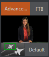
Click the label above the Effect icon and use the Media Browser to select the Advanced Tracker effect from the Default group.
-
Add the clip named Tracking Example.mov from the (NTSC or PAL)>Tracking file group to the playlist for DDR 1.
-
Enable Loop mode for DDR 1.
-
Add the clip named River Bridge.mov (or another clip you like better) to DDR 2, set it to Loop as well.
-
Add an attractive full frame graphic to the DDR 3 player.
-
Select M/E 1 on the main Switcher’s Program row, to make it easy to view the result of the following steps.
-
In the M/E 1 tab, select DDR 1 on the input A row.
-
Select DDR 2 as input B.
-
Select DDR 3 as input C.
-
Double-click the monitor for DDR 1 to open its Input Configuration panel.
-
Continue to configure both LiveMatte and the Tracker for the video clip in DDR 1:
-
In the LiveMatte tab, click Reset to update the keyer settings to their defaults, and enable the LiveMatte switch at upper-left.
-
Use the Scrub bar under the playlist in DDR 1 to advance through the clip until the colored card is visible in the frame.
-
Switch to the Automation tab, and expand the Tracker control group.
-
Click the Color picker (eyedropper) keep the mouse button held down, and drag the pointer over the color card and release to assign that color to the Tracker for DDR 1.
-
Boost the Tolerance setting to 34%.
-
Press Play for both DDRs.
On the Program monitor, you should see the talent clip overlaid on the image from DDR 3 (LiveMatte is turning the green pixels in the DDR 1 clip transparent). You’ll also see imagery from DDR 2 displayed wherever the (originally) blue card appears in the frame.
What’s happening is that the Advanced Tracking effect is applying the values from the (DDR 1) Tracker for a secondary iteration of LiveMatte. Our LiveMatte settings cut away the green, revealing the C layer behind. Afterward, the blue color range is also keyed out, revealing the B source through the transparent region where the blue card is.
Up to this point, the effect takes advantage of the Tracker color values, applying them as a secondary keyer – but we haven’t yet done anything with the actual motion data the Tracker is supplying. Let’s do so now.
-
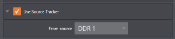
Click the Position button for input B to open the Position Panel for that layer.
-
Select DDR 1 in the Use source Tracker menu.
-
Enable Follow Tracker.
The result on your Program monitor should look much like: Full motion video appears wherever the orange card appears in the foreground clip. This is the standard setup for the Advanced Tracking effect, though it’s possible to use it in different ways too.
Note: Advanced Tracker 2 provides much improved compositing. (The original effect is provided for legacy purposes, but might also produce a better result in rare cases where a source has embedded transparency). Among other benefits, the newer effect performs spill suppression at the edges of the tracked region. Using the size (etc.) parameters of the tracker, the region being tracked can be made slightly larger to taste, to moderate this effect.

Test the effect of the Scale, Rotation, and Aspect controls in the Tracker tab for DDR 1 (you can double-click the DDR 1 monitor to open this panel).
Utilities
-
Follow the procedure from the Advanced Tracker section above, and replace the current effect in M/E 1 with the Show Alpha effect from the Utilities group.
Applying this effect immediately causes the display on the Program monitor to update, showing the content of the alpha channel for input A (Input B is ignored).
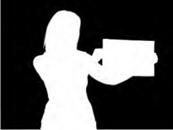
The current input A source is keyed, so the effect displays black on Program out wherever transparency exists in the foreground, white for full opacity, and shades of gray for in-between blends. With this in mind, it won’t be hard to guess what Show Inverse Alpha does. In contrast, the Show Color effect in this group passes the full color output of LiveMatte prior to being multiplied by the alpha channel (it might seem as though this would be identical to the original source, but you may notice subtle differences. This is because of the Spill Suppression processing).
Other effects in the Utilities group
Color Correction: Replace the current effect with the Color Correction effect. M/E 1’s output on the Program monitor is now rendered in monochromatic grayscale. Drag the T-Bar down to affect the M/E’s color saturation. Click the mouse on the Position button below the T-Bar and drag to modify Hue.
Make Legal: Ensures the output of an M/E is within broadcast signal tolerances.
3D
The Anaglyph (Red, Cyan) effect found in the 3D category is a special purpose tool.
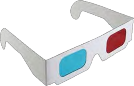
The anaglyph method of displaying 3D imagery depends on stereo video inputs that are filtered and composited into a single output stream. In turn, this combined stream resolves into 3D when viewed through special glasses with red and cyan (blue-green) filters for left and right eyes respectively. Viz Vectar Plus provides easy access to anaglyphic technology by means of the Anaglyph effect. The effect combines two video inputs selected in an M/E. 3D output can then be switched easily like any other source. No complex configuration steps or tricky control surface operations are required.
Photoshop Blend
The effects in the Photoshop Blend folder apply well-known blending modes to the A layer in the M/E as these are blended with the B layer. The resulting compositions can serve many purposes, such as adding animated bokeh style overlays using DDR clips or adding interest to still overlays such as vignettes or titles.