Viz Vectar Plus User Guide
Version 1.3 | Published November 18, 2022 ©
Input Configuration
Open Input Configuration by any of the following methods:
-
Double-click the monitor viewport for a Switcher input.
-
Click the Configuration (gear) icon shown at lower right when the mouse pointer is rolled over above the viewport.
-
Two-finger tap the viewport (if you have a touch-screen).
-
Right-click a Switcher input button and select the Configure menu item.
Input Tab
Any external NDI source or (if available) a local hardware source connected to one of the system’s hardware input connectors, can be flexibly assigned to any Switcher input.
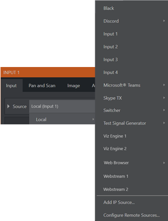
Source
Use the Source drop-down list to assign one of the many sources available to the corresponding switcher input. Available video sources are grouped under labels named for the device supplying them.
The Local group in the Source menu includes those sources connected locally to the system’s hardware inputs (for example, IP and SDI BNC connectors), any other local hardware sources detected (such as a webcam) and Black.
IP Source
The Add IP Source option is near the bottom of the local source list. Clicking Add IP Source opens the IP Source Manager. Adding entries to the list of sources shown in this panel causes corresponding entries for new sources to appear in the Local group shown in the Source menu of the Configure panel:
To add an IP Source select a source type from the dropdown list provided.
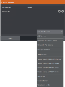
This opens a dialog suited to the particular source device you wish to add, such as one of the numerous supported PTZ camera brands and models.
Additional protocols have been added to provide more options for video sources. RTMP (Real Time Message Protocol), a standard for delivering streams to your online video platform. RTSP (Real Time Streaming Protocol), used for establishing and controlling media sessions between end points. SRT Source (Secure Reliable Transport) is an open source protocol that is managed by the SRT Alliance.
SRT can be used to send media over unpredictable networks, like the internet.
Note: It is recommended to first get the stream working, then copy the URL into Viz Vectar Plus.
The IP Source manager panel displays the selected source, here you can edit by clicking the gear to the right of the source name, or click the x to remove the source.
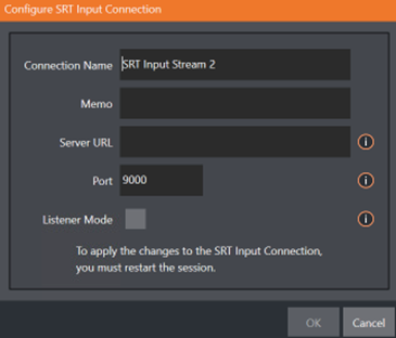
Memo: Enter a brief description for later reference.
Server URL: The server URL must be the public IP address of the remote source, either as a numerical address, or named such as entrypoint.cloud.website.com.
Port: Each SRT stream must have a unique port number. This can be any valid port, but ports in the 9000 or 10000 range are common.
Listener Mode: the stream connects to the Caller machine, then waits for it to initiate streaming. Otherwise, this machine is the Caller and the other side must be the Listener.
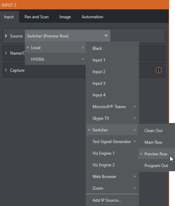
Program Re-entry
This feature enables any video input setting in local IP source to select Program Out, Clean Out, Preview Row or Main Row (and allows that input to be used for instance, within M/Es to add additional overlays or other layer combinations).
The main PGM feed can be re-used for other outputs where content can be added and modified to adapt stories with graphics, cropping, aspect ratio, and more. This feature empowers you to make multiple versions of your show easier than ever.
The assignment of one of the various types of source to a Switcher button (for example, Input 1 on the Switcher) is made in the Input Configuration panel, introduced in Configuring AV Output.
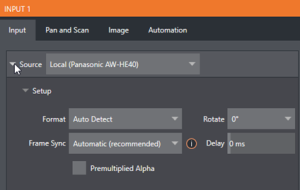
Setup
Format
Expand the Source > Setup control group to reveal a Format list for the type selected in Source. Defaults is Auto.
For an NDI source, no further settings are required.
Rotate
To assist non-traditional sessions with unusual Switcher sources (for example, non-landscape mobile device output) each input has a Rotate menu, which also includes Flip options.
Device Webpage
For network connected sources (such as NDI sources), a Device Webpage button may appear just right of the Source menu. Click this button to access the remote device’s own configuration webpage.
Delay
At times, typically due to upstream processing and architecture, video may arrive at the system’s inputs ahead of the corresponding audio. The Video Delay feature allows you to compensate for these issues to establish A/V sync.
Frame Sync
By default, Frame Sync is set to Automatic for all external source types, allowing you to work with a wide array of potential video sources without concerns about video timing.
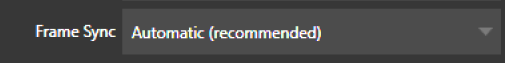
This option (Automatic) enables the full array of timing correction tools available to achieve smooth and accurate frame timing in your productions, including features that correct for issues caused by less than ideal networks.
The next menu option (On) enables full-time frame synchronization and may well suffice in some video pipelines. This alternative has the benefit of ensuring the lowest throughput latency possible on a video switcher using frame-sync (2-3 frames).
Premultiplied Alpha
If you are supplying imagery (video sources, video clips, or still images) that support transparency by means of an embedded alpha channel, your choice here is important. There are two flavors of alpha channel pixel encoding. The first is often called straight, or may be referred to as non-premultiplied. Unsurprisingly, the alternative is premultiplied.
The Premultiplied Alpha switch is off by default. Making the correct selection is necessary for correct compositing over other imagery.
Low Bandwidth
For NDI source only. This allows you to force the sending device to a lower quality video stream. This compromise is acceptable when the source is not intended to be displayed full screen. Useful in network settings with limited capacity (such as WiFi).
PTZ Control
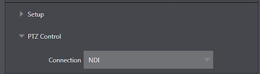
For many source types, a PTZ Control menu is shown in the Source control group. The default control Connection type is NDI which, assuming you are configuring an NDI source, makes life a lot easier because there is nothing else to configure.
Otherwise, if you must select a legacy control connection type like RS422, etc., or perhaps a non- NDI network connection, additional controls may be shown in this group to let you configure things like Baud Rate, Com Port, IP Address, and the like.
Name/Comment
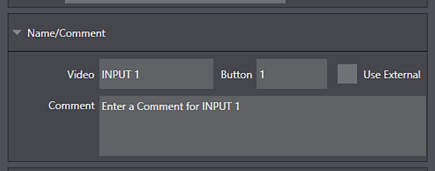
Expanding the Name/Comment control group reveals text entry boxes that allow you to provide labels for your video sources – specifically, the Video entry appears beneath viewports in multiviews and some menus (where space permits), and the short Button text is used to label Switcher buttons.
Enable the Use External switch to automatically pass the channel name for a remote source such as an SDI router or NDI channel to the Video label field.
The Comment entry lets you enter memo text that can serve as memory aids, but or another very valuable purpose, too. Specifically, the values entered in these two fields supply the values for special DataLink keys. Among other things, the values from these DataLink keys can be used to update text values in title pages, or to add information to the filename of recordings.
For example, you could use a macro to automatically display a title page briefly any time you switch cameras. The Name and Comment entries for inputs update the values assigned to DataLink Keys named %PGM Source Name% and %PGM Source Comment% based on Program row selections. You might enter Bill Jones, CEO as the Video name for a camera, and Megadyne Computronics, Inc. as the Comment.
Continue to give unique values to inputs in similar fashion. Then enter %PGM Source Name% on the first line of a title page, and %PGM Source Comment% on the second line. When you change cameras, your macro displays the page, correctly identifying the talent based on the input Name and Comment.
Capture
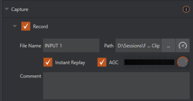
Each Switcher source has a Capture group in the Input tab. This control group shows settings and options for grabbing still images and, for appropriate sources, recording. These important capabilities are discussed in full in Record, Grab and Replay. The controls shown in are detailed in Record.
PTZ/ Pan and Scan Presets
Another control group appears on the lower part of the Input tab when appropriate. This group may be labeled either PTZ Presets or Pan and Scan Presets, depending on the source type (one could hardly be blamed for referring to the latter as virtual ptz presets).
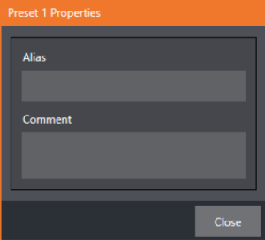
In either case, the features and options presented in this group are similar. At the top, there are 16 numbered preset slots. Rolling over these slots reveals two gadgets: Click the snapshot (camera) gadget to store or update a preset. Click the configuration (gear) gadget to show a Preset Properties panel, with two text boxes labeled Alias and Comment.
The entries in these two text boxes, like the Name and Comment values discussed earlier, provide the values for special DataLink keys that store the values from the last PTZ preset applied, as follows:
-
PTZ PGM Alias
-
PTZ PREV Alias
-
PTZ PGM Comment
-
PTZ PREV Comment
Tip: These DataLink keys can be very useful in settings like a town hall meeting, where you might use different PTZ presets to zoom in on a few different council members. In such a case, the last preset applied could update the data shown in a lower-third title overlay.
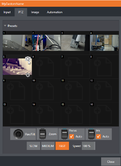
A set of controls located below the preset bin allows you to control connected PTZ cameras, or to affect sources supporting Pan and Scan features in similar fashion (you might think of these sources as providing a sort of virtual PTZ functionality). SLOW, MEDIUM, and FAST preset buttons complement the numeric Speed control slider at right. These affect the speed of the transition from the current position to newly selected preset.
The Options group, when expanded, reveals White Balance options along with a menu that allows you to invert the operation of the Joystick on individual axes (both in the interface and on connected hardware control surfaces).
Note: Focus, Iris, and White Balance features are only shown when a PTZ cameras is connected to the input. However, features in the Input Configuration panel’s Image tab, discussed next, can provide similar functionality to White Balance automation.
Image Tab
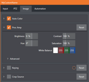
The Image tab in the Input Configuration panel hosts a set of features that provide extensive color control processing, chromakeying, and cropping options for every video source.
Auto Color
Lighting conditions can change dramatically during many live events, especially those held outdoors. Adding to this problem, production usually involves multiple cameras and, all too often, these may not have uniform color characteristics. Ensuring consistent color when switching from one angle to another, avoiding unwelcome brightness or color shifts as evening falls or when a cloud obscures the sun briefly can be troublesome, and expensive.
Auto Color, a unique feature capable of dynamically adapting the color characteristics of your video sources as lighting conditions vary, can minimize these problems. For many productions, enabling Auto Color is all it takes to produce a show that looks amazingly consistent.
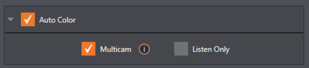
Multicam
By default, each camera with Auto Color enabled is processed uniquely – without reference to other sources. Often, though, even greater consistency can be achieved by treating sources in similar illumination environments as a group. Enable Multicam for several cameras causes Auto Color to evaluate and adjust these cameras in unison. You might, for example, enable Multicam for courtside cameras in an interior sports venue, while treating exterior or studio feeds individually.
Listen Only
The Listen Only switch allows you to include a source in the Multicam group without adding its own feed to the group evaluation. Thus, a camera trained on a giant purple dinosaur can be automatically corrected without disproportionately biasing the group evaluation and Auto Color correction. Alternatively, one might enable Multicam for a number of sources, turning Listen Only on for all but one camera – effectively making that camera the color reference all other cameras in the group follow.
Note: The Proc Amp, discussed next, is downstream of the Auto Color system. This allows you to apply further manual color adjustments to your individual sources, whether for fine tuning or to achieve a specific “look”.
Proc Amp
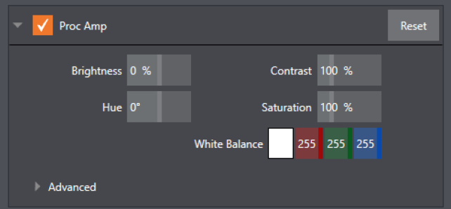
A switch at the top of the Proc Amp control group toggles the feature on/off. Other controls operate as follows:
-
Brightness: Adjustment range from -50 to +50 IRE (the default being 0). As reference, the full luminance range of the visible portion of a video signal can be thought of as 100 IRE units (named for the Institute of Radio Engineers) – ignoring minor regional variations.
-
Contrast: Adjustment range from 25 - 400% (default 100%).
-
Hue: Adjustment range between -180° and +180°. Adjusts the master color of the video signal from the attached source, swinging the entire image through the color wheel’s spectrum.
-
Saturation: Adjustment range from 0-500%. Zero saturation results in a black and white picture; increased saturation results in richer colors. High saturation values can exaggerate the color portion of the signal
Warning: Over-saturated colors are considered illegal for broadcast transmission and may result in display problems on some devices.
Tip: Proc Amp adjustments are applied downstream of LiveMatte, which can help when composing greenscreen shots to match a background or LiveSet.
-
White Balance: To automatically white balance, click and hold the mouse button on the Color well, and then slide the eyedropper pointer onto the monitor for the corresponding source. Release the mouse button over a part of the image that should appear as white after processing.
Advanced Color Controls
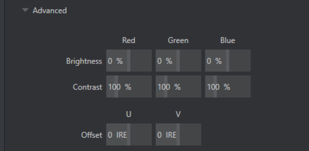
This secondary control group is revealed when you click the expander (triangle) beside its label. In addition to per color channel (RGB) Brightness and Saturation sliders, it adds U Offset and V Offset controls.
-
The U portion of the video signal carries blue and yellow color information. Rotating the U Offset knob clockwise shifts the signal toward blue, while a counter-clockwise twist shifts the signal toward yellow.
-
The V portion of the video signal carries red and green color information. Rotate V Offset clockwise to shift the signal toward red and counter-clockwise to shift the signal toward green.
Tip: Your system provides Waveform/Vectorscope monitors, which are an invaluable aid to you for accurately calibrating your video sources.
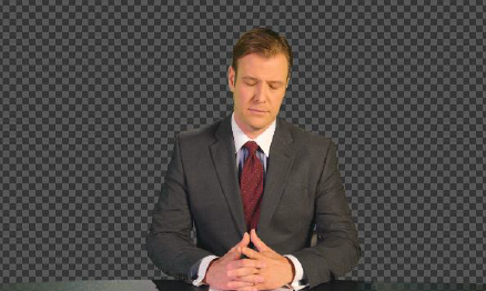
Keying
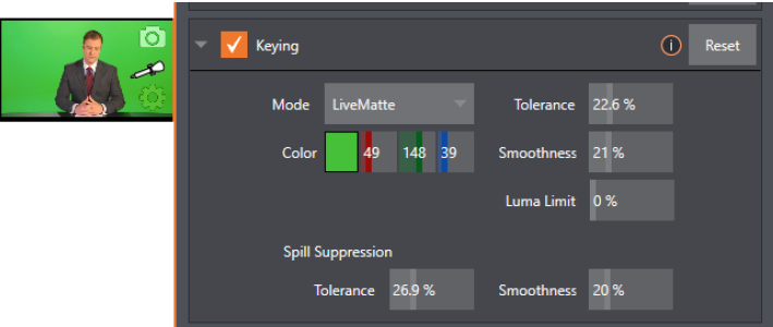
The Keying control group in the Image tab hosts LiveMatte, a powerful real- time keying system for live production. Keying is a popular and powerful method of compositing multiple images, whether photos, video clips or live camera streams.
The process involves eliminating a portion of the video image (effectively cutting a digital keyhole in it) to reveal a user-defined background scene.
LiveMatte’s controls are simple, making a great deal of complex digital manipulations easy to use. Even so, much can be said about getting the best results. For that reason, we have devoted a whole chapter to LiveMatte.
Tip: When LiveMatte, Proc Amp, or Crop settings are active for a source, bright green, blue and yellow indicators are lit under its monitor.
Crop Source
It is very common for a source to be supplied with unintentional inclusions; these are often items that remain after chromakeying is applied, but which need to be removed along with the background (Common examples include microphones or lighting fixtures dangling from above, or perhaps a harsh crease, blemish or tear in the background screen). Or, as is frequently the case, the source video itself may have a few pixels of black or video noise along one or more of its edges.
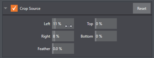
The settings in the Crop Source control group can be used to remove such unwanted garbage from the scene, and other purposes, too – such as to isolate a portion of the screen for use as a Picture in Picture overlay.
Numeric controls in this group let you define margins for each side of the frame. Drag left or right on the number fields to adjust the values interactively or click a field to enter an exact value using the keyboard. The region defined by these controls is completely removed. Use the Feather setting to soften the edges.
Tip: For added convenience, similar cropping tools are available separately in the Position panels of DSKs, along with the Key and, for LiveSet Effects, each layer’s settings for MEs.
Automation Tab
Automation is one of those wonderful things that really transform your workflow. The Automation tab, located in the Input Configuration panels for all video sources is one of several places where related features can be found.
Macros (discussed in Macros and Automation) might be viewed as the basic building blocks of automation. Macros can easily be recorded and edited, and equally easily they can be triggered by a keystroke shortcut, control surface button, or similar means; but that isn’t really automation, is it? It’s actually a manual operation.
Somewhat obviously, automation should happen automatically based on predetermined criteria. The automatic transmission in your car shifts all by itself when certain conditions are met. In similar fashion, the features of the Automation tab allow you to predetermine what happens when certain conditions are met. Consider the State Change control group.
State Change
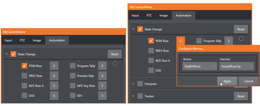
Click the E button next to a one of the state options to assign macros that are executed on specific Switcher operations that affect the specified state.
For example, the accompanying images depict macros that control the volume level of the SOUND player. Whenever Camera 1 is newly selected on the Switcher’s PGM row, the Active macro runs. Conversely, replacing Camera 1 with a different PGM row selection executes the Inactive macro.
Tip: The E on the button is short for Event.
The State Change implementation thus allows you to automate all manner of operations based on such things as the following:
-
Program or Preview row selection.
-
Displaying/ hiding the source in a DSK or KEY channel.
-
Selecting/de-selecting it on an M/E’s A row, or any M/E row.
-
Showing or hiding a source on the Program or Preview output.
This is immensely powerful, and lends itself to endless applications, such as (to suggest just a few):
-
Automatically fly in a title as you switch to remote sources, and remove it after a specified time.
-
Select a different Audio Mixer preset automatically when you switch from viewing a source in the B monitor of a double box effect on Program to displaying it full-screen.
-
Then change back to the original audio setup when you switch back to the anchor desk.
The possibilities are truly endless.
HotSpots
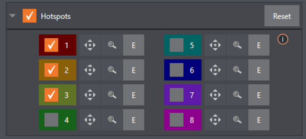
The next control group in the Automation tab is devoted to Hotspots – another powerful and interactive automation feature. A Hotspot is a user-defined region of the screen that (when active) detects opacity changes inside its boundaries (for which reason, Hotspots require LiveMatte to be enabled to work properly).
With LiveMatte properly configured, the Hotspot feature can trigger a macro when opaque pixels are newly detected in an active Hotspot.
For example, someone in a greenscreen set can trigger a macro by walking into a location in the frame where a hotspot has been defined. A second macro when all opaque pixels (the talent) moves out of the defined hotspot zone. All manner of creative implementations are possible.
Tracker
The Tracker control group provides real-time motion tracking features. This feature allows you to choose a colored region of the video frame using tools similar to those found in the LiveMatte tab.
The tracked region is defined by choosing a primary Color using the color picker tool. The Tracker follows this region as it moves and shifts within the frame over time, and outputs the motion data for downstream application. Tracker output from one source can be used to dynamically modify the positioning of other video sources, when configured to do so in their individual Position panels.
Adjusting Tolerance
Click the eyedropper, and, while holding the mouse button down, drag the pointer over top of the monitor for the source you want to track. The Tracker’s color swatch updates as you drag, until you release the button to finalize your selection.
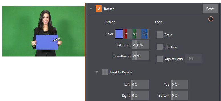
To assist you while making adjustments, a yellow rectangle is overlaid on the video to show the effect of the current Tracker settings. Watch how this overlay is affected by adjustments you make to the Tolerance value for the Tracker. Raise or lower the Tolerance value until the result is steady, not jittering or jumping about.
Tip: The yellow overlay disappears when you close the panel (or disable the Tracker), but you can show it full-time if you wish. To do so, right-click the desired viewport, and enable Tracking Markers from the Overlays options group in the menu.
Smoothness
The Smoothness setting works just like the LiveMatte feature with the same name. Its impact on tracking data output may seem minimal, but it can be important when used with the Advanced Tracking effect in M/E panels.
Lock
These are controls that permit you to Lock certain Tracker attributes, preventing them from changing in the scene.
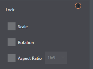
-
Lock Scale to prevent the Tracker from automatically compensating when the scale of the tracked region grows or shrinks during motion.
-
Likewise, when Rotation is locked, the orientation of Tracker output is constrained.
-
The Aspect Ratio lock forces the Tracker to conform to a square (1:1), or rectangular (4:3 or 16:9) shape.
Tip: Locking channels in this manner makes it easier to obtain a steady motion track; but often, your choices are dictated by creative requirements.
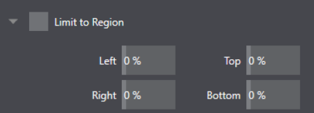
Limit to Region
The Tracker is designed to follow the largest shape in a frame that meets the defined color criteria. At times, similar colored articles or inclusions in the frame can interfere with Tracker output.
The settings in this group allow you to limit the area of the frame the Tracker monitors, which can help you sidestep this issue.