Viz Vectar Plus User Guide
Version 1.3 | Published November 18, 2022 ©
Input Connections
Connecting a Video Router
Viz Vectar Plus responds to your changing requirements by removing the traditional boundaries of media formats, I/O, channels and delivery. It is a one-size-fits-all digital media environment for content creation to Internet, mobile and television distribution.
With the appropriate software installed, your system can control and access output from router models supporting NDI matrix router, DeltaCast, Bluefish444, Matrox, Black Magic Design®, Grass Valley® Native Protocol and many more.
To set up a router
A basic setup with any of the above supported cards would be:
-
Connect the ethernet controlled router to the same network as the system, then connect one (or more) of the router’s video outputs to external SDI inputs with matching numbers, using suitable video cables. (For example, by default router output number 3 would be connected to Input 3 for control communication between the devices to be properly linked).
-
Click the Shutdown icon on the Home page (Launch screen) and then Administrator Mode at the right.
-
In Administrator Mode panel, click Exit to Windows.
-
Navigate to the folder:
-
C:\ProgramData\vizrt\ VectarPlus\Configuration
-
-
Edit the file named router_setup.xml.
This file is where you add the routers you wish to connect. Each router is identified by an entry you insert between the starting and closing “config” tags, as explained in the file comments.Example entry:
<grassvalley ip="10.28.1.128" port="12345" name="AJA KUMO"/>
-
Save the file.
-
Re-launch the system.
Note: The system communicates with routers using individual IP address and port numbers, allowing multiple routers to be connected simultaneously. File comments explain how you can bypass the default 1:1 mapping of router outputs to inputs when required and prevent accidental changes to inputs that are displayed on Program output, along with other extended configuration options. If you assign names to router inputs or outputs in this file, make sure the names for each are unique.
Some routers allow each router input to be provided with a unique name. In such a case,Viz Vectar Plus may be able to access that name and use it for Switcher buttons as appropriate.
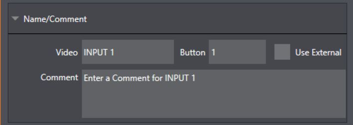
To enable this behavior, check the Use External (name) switch in the Input Configuration panel. See Input Configuration for more detail.
Connecting a Control Surface
Please refer to section Connection and Configuration.
Black Magic Design® Auto-Detection
For backwards compatibility, these routers are by default, auto-detected at connection.
Black Magic® routers may use a USB control connection, or a network connection. The router’s firmware must be up to date.
If detection fails, please contact BMD support for assistance.
To disable auto-detection
You can optionally disable auto-detection . Disabling auto-detection enables further configurations to be manually entered into the file.
-
Edit the XML configuration file described above in procedure To set up a router.
-
Add the line below to the <config> section of the file.
<blackmagic_config discovery="false"/>