Viz Vectar Plus User Guide
Version 1.3 | Published November 18, 2022 ©
Connection and Configuration
Connect the control surface unit to the same network your Vizrt live production system is on. Both Viz Vectar Plus control surfaces require a standard, 3-prong AC power connection. You need to pair a control surfaces with a specific live production unit to control, as described next.
Note: The control surface and your Viz Vectar Plus should be connected to the same subnet.
Pairing Systems and Surfaces
Viz Vectar Plus auto-detects compatible control surfaces on the same network. Often there is only one such surface, which makes setup easy. At other times, though, you may be in an environment with more than one surface, more than one live production system, or both of these conditions.
Control Surfaces Utility
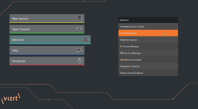
To help you manage these control connections, the Control Surfaces configuration utility is included in the Launch panel’s Add-Ons menu.
-
Click the Add-Ons button on the main menu on the Home page in the Launch pane to show the list of installed add-on applications.
-
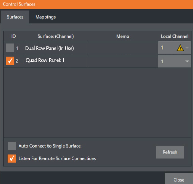
The utility automatically identifies and lists qualified control surfaces it finds on the network.
-
Each surface discovered is listed in a numbered row. The ID number for the row is not permanently associated with a particular surface, and may change as surfaces are added to or removed from the network. The ID number serves a very useful purpose. If you look at the top-left LCD display panel of an un-paired control surface when this utility is open, its ID number is temporarily shown. This makes it easy to match an entry in the panel with a specific physical surface.
-
Once you identify the surface you want to use, check it in the list to claim it for the local system (the steps in Setting the Channel complete the communication connection to the surface).
-
You can also enter a brief description (Master Control CS) into the Memo field, for later reference.
Setting the Channel
A Local Channel menu is provided for each surface: More accurately, for each echelon, or two stripe pair on the surface (see Control Schema).
The Channel menu controls just one of two related channel settings – this one (on the local host), and another channel used by the control surface itself. These combine to let you connect to and control alternate live production systems.
Tip: You might think of the control and system channels as being like the channel settings of two walkie talkies (2-way radios). For two-way radios to connect, both units must be on the same channel. Similarly, the channel selection displayed in this software pane tells the local unit to communicate with the selected (check-marked) control surface on the channel you choose. Of course, the control surface must also be set to the same channel for successful communication.
The Control Surface utility identifies the channel each control surface is on by a number from 1-8 after the colon in the Surface: (Channel) column.
Normally, you can set the Local Channel to match this value (a Warning is shown if the channel the surface is set to does not match the Local Channel).
If you find it necessary to modify the channel the control surface is set to, proceed as follows:
Hold down the SHIFT, CTRL and ALT buttons on the control surface at the same time for a couple of seconds to enable channel select mode. The left-most LCD display in the first stripe in the echelon updates to show channel selections, and a button in the PGM/A row lights to show the current channel. Tap another button in the row to change the selection.
Note: For the four-stripe Viz Vectar Plus L panel, you must repeat this operation in order to match the second echelon’s channel setting to that of the first. Press and hold the number pad buttons labeled 1, 2 and 3 in the third stripe (rather than SHIFT, CTRL and ALT) in this case; then make your channel selection using the A button in the PGM/A row of the third stripe. With these settings you can, for example, set one system to listen a certain control surface on channel 1, and set a different unit to listen to the same control surface on channel 2 – then easily go from controlling one system to controlling the other by updating the surface channel setting.
Button Backlighting
Press the LAYER SELECT B and D buttons together, and keep them pressed down.