Viz Vectar Plus User Guide
Version 1.3 | Published November 18, 2022 ©
Calibrating Video Sources
The obvious disparity between neighboring televisions on display in a store amply demonstrates that even identical (and brand-new) video devices can differ dramatically. When mixing multiple cameras, we need to ensure that their output matches. Switching to a camera with obviously different color characteristics will be seen as a glaring error by your viewers.
Even when we restrict matters to a single unit, color characteristics can change as the system warms up, and as it ages. For this reason, it’s important to allow a device to warm up before attempting to calibrate it.
Setting Black and White
Naturally, the color range available for transmission and recording is bounded at the upper level by white and at the lower level by black. Anything else falls somewhere in-between.
Consider what happens if you gradually raise the brightness control on your television. Beyond a certain point (and unlike claims made for laundry detergent) your whites do not become whiter. They can’t – the upper limit (white) is firmly fixed. Instead, parts of the image that are nearly white are boosted, eventually also becoming white. Meanwhile, black portions of the picture are tending towards gray. Since white cannot become whiter, and black has become gray, we could say that the dynamic range of the image has been narrowed. The net result is a less vibrant image.
The same thing is true for video from your cameras. If the black and white levels from the camera are incorrect, you are effectively losing either shadow or highlight detail. For this reason, the first thing many do is calibrate their camera for correct levels.
Waveform Monitor
From days of old, for video engineering purposes the scale between black and white was defined in IRE units (IRE being an acronym for “Institute of Radio Engineers”). White was pegged at 100 IRE. For PAL (and NTSC-J) countries, black was defined as 0 IRE. For NTSC lands, black properly sat at 7.5 IRE.
Thankfully, the day of strict adherence to these analog video concepts has virtually disappeared. Today, confirming that the black and white levels your camera is sending are correct is as simple as sending first black, and then white (or the brightest past of your scene, and reading values from the scale alongside the Waveform scope.
Tip: Your system automatically compensates for the traditional 7.5 IRE black (also known as “setup” and “pedestal”) in SD format NTSC sessions.
Connect your camera to the correct input, block the lens so it receives no illumination, and check the level shown in the Waveform monitor. Generally, it should be 16 on the 8-bit scale.
To check white, use either the brightest part of your scene or a white card, ensuring that it is evenly illuminated with the same lighting your main subject will receive. Move in or zoom to fill the viewfinder with this, and confirm that the Waveform monitor is showing 235 on the same scale. Otherwise, you might try using your camera’s Auto White Balance feature with the white card – your camera manual will provide instructions. Afterwards, check the black level again.
Some professional cameras offer full manual controls for white balance and/or black level. Use these as instructed to ensure your camera is providing the correct white and black levels.
If you cannot make source adjustments, or can’t get it quite right by these means alone, you can use the Brightness and Contrast controls in the Proc Amp for that input to tweak black and white levels (It is best to perform adjustments at the source if possible).
Adjusting Color
We’re going to move into color calibration next, but first we can actually use our black and white signals for some further tests.
Vectorscope
While we’re still working with black and white levels, we can introduce the Vectorscope, and perform an initial test of the camera’s color balance.
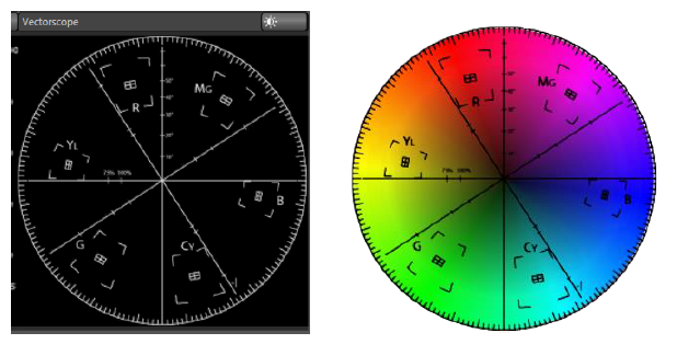
A vectorscope can be likened to the familiar ‘color wheel’ which sweeps radially through the colors of the spectrum – yellow, red, magenta, and so-on, around the arc of a circle. Colors are more progressively intense (saturated) towards the outside of the circle, while color saturation is zero at its center.
As it happens, from the vectorscope point of view, neither black nor white properly have any color saturation. Thus, with the lens cap on (or with a white card filling the viewfinder), the vectorscope should show only a small fuzzy trace at its center. If the fuzzy dot is off-center horizontally or vertically, this would indicate that the camera is incorrectly calibrated, actually tinting gray areas.
When the trace is off center, the direction and distance of the offset tells us what sort of tint (and how much) is represented by the deviation. You may be able to use the color controls at your camera to correct for this offset, or you can use the Proc Amp’s U Offset and V Offset controls to do so (as always, source controls are best). Adjustments to U Offset move the trace left or right, while V Offset changes adjust its vertical position.
Color Metrics
At this point, we’ve assured ourselves that the signal from the camera is neither too bright nor too dark, that its output falls within broadcast legal luminance limits, and that the black & white part of the signal does not have an unwanted color cast. We haven’t done anything yet to assure our reds are red, not slightly brown, or that our blues are not slightly green or magenta, etc. The Vectorscope can provide much more specific information about your cameras color signal. Let’s see how it can assist you to ensure your colors are accurate.
Using Color Bars
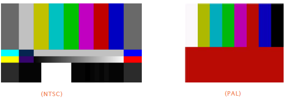
You’ll no doubt have seen the familiar color bars used as a standard reference for video signal calibration. Two examples are shown here: NTSC is an example of the color bars used in NTSC countries, while PAL is common throughout European nations.
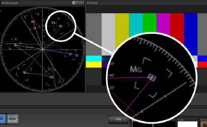
You can use color bars in conjunction with Waveform and Vectorscopes to make sure the video supplied to is consistent, accurate and broadcast legal. Most video cameras are capable of displaying color bars. Check your camera manual to see how to display these (given a choice, use 75% bars). Then look at the Vectorscope to see how it traces the individual colors comprising the image.
The Vectorscope graticule has six distinct rectangular targets, one each for Yellow, Red, Magenta, Cyan, Blue, and Green. The targets are small rectangles with a cross-hair superimposed on them. When a source is properly calibrated, the trace from the different colored segments of the color bars displayed will fall right inside their individual targets.
If the trace vectors do not line up as they should even after performing a white balance at the camera, you can use Proc Amp controls to tweak the signal.
Adjust the Hue control to rotate the vectors around the center point to line them up correctly on their respective targets. Increasing Saturation will move the trace further out towards the edge of the scope. Decreasing Saturation lowers color intensity, bringing the trace back closer to the center.
Hint: You should repeat the steps above for each connected source, to ensure a perfect match when switching from camera to camera during your live productions.
At this point, your video signal should be reasonably accurate, and broadcast legal. Naturally, there are other devices between that signal, you, and your viewers. Let’s discuss ways to calibrate downstream video monitors to ensure that you see your video at its best.