Viz Vectar Plus User Guide
Version 1.3 | Published November 18, 2022 ©
Advanced Configuration
The controls for each inputs (including internal audio sources) as well as the Effects, Stream, Aux and Master output groups, include a Configuration (gear) button shown when you move the mouse over the input label.
-
Clicking the C onfiguration (gear) icon opens the advanced Audio Configuration panel, offering many more important features and controls.
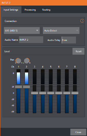
Input Settings Tab
Connection Panel
Audio Delay
Audio and video arriving at inputs in sync maintain sync throughout the system to output or recording. However, you should note that upstream issues can cause video to arrive at system later than the corresponding sound. To mitigate this sort of external problem, the Audio Mixer provides an adjustable Audio Delay feature (for example, many cameras support simultaneous digital and analog audio output. In-camera processing can delay digital A/V output, resulting in analog audio output actually leading the digital output by a meaningful measure).
Gain
On selected models, and usually for sources set to Mic input type, Gain knobs may appear in the Input Settings tab to allow you to compensate for microphone variances.
Pan
The Audio Configuration panel also provides Pan controls. It adjusts placement of sound from source audio channels on the stereo channels comprising the audio mix(es). Using Pan, you can place all or part of channel 1 onto channel 2, and vice versa.
-
When Pan is set to the extreme left position for channel 1, its audio is sent exclusively to the first channel for the Input 1 group.
-
Centering the Pan 1 knob splits the sound from Input 1 equally onto channels 1 and 2.
-
Sliding Pan for channel 1 fully clockwise results in that source only being audible on channel 2.
Pan also modulates the sound levels on the left and right channels so that the overall volume neither rises nor drops as a result of adjustments.
Note: Pan is not the same as Balance. The balance control in a stereo system varies the relative level of the left and right channels, but sound from the left channel never comes out of the right speaker, or vice versa (pan does permit this).
Processing Tab
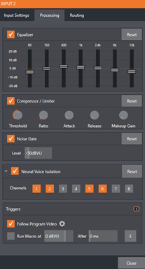
Equalizer
The seven-band equalizer allows you to shape sound to taste, accommodate sources with different acoustic characteristics, minimize feedback or roll off unwanted parts of the audio spectrum.
Enable or disable the Equalizer using the switch beside the label above its control group. The vertical sliders attenuate or boost the tonal range centered on the frequency shown at the top. The effect applied falls off gradually as sound draws closer to neighboring frequencies on either side. Click Reset to return all sliders to 0dB.
Tip: Reducing or increasing the level of one or more tonal bands affects the overall output level as well. You can trim the main level setting for the affected input or output.
Compressor Limiter
The Compressor/Limiter is capable of preventing clipping (see Output and Primary Bus Controls) from unexpected peaks or transients, and making talent sound better, bringing voices, music and other audio sources into an optimal dynamic range.
Compression takes the form of a subtle, almost imperceptible modulation of the sound level to bring it into a more convenient range, and a limiter is essentially just a compressor set to a high ratio and, generally, a fast attack time. Audio engineers typically consider compression with a ratio of 1:1.
-
Threshold: Sound above the set Threshold level is compressed. The amount of compression and the manner in which it is applied are both dictated by the other settings.
-
Ratio: A Ratio of 4:1 means that if input level is 4 dB over the threshold, the output signal level after compression is just 1 dB over the threshold. The gain (level) is reduced by 3dB. Very high ratio settings are the reason the word limiter is part of the label for this feature. The highest ratio setting effectively reduces any signal that would rise above the threshold all the way down to the threshold level (with the exception of a brief period during a sudden increase in source loudness, as dictated by the Attack setting).
-
Attack: Attack is also in milliseconds. The setting represents the amount of time it takes for the gain to change by a specified amount. Shorter values are more aggressive, while longer values are more subtle (and tend to be less noticeable to the audience).
-
Release: Refers to the speed with which the compression effect is removed as a source signal falls back on its own so that it no longer exceeds the Threshold.
-
Makeup Gain: The Gain control allows you to compensate, bringing the post-compressor/limiter signal back to a comfortable nominal range.
Noise Gate
The Audio Mixer’s advanced options panel also include a configurable Noise Gate for each audio source, as well as all outputs. This lets you ensure that unwanted low-level sounds are prevented from inadvertently intruding into the mix.
Neutral Voice Isolation
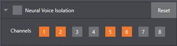
Used to enable and disable noise reduction.
-
Check the Neutral Voice Isolation box and select your channel(s). The AI audio can be individually selected for each channel of an input.
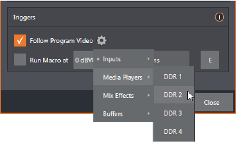
Triggers
Several different per-input automation features are found in the Processing tab.
-
Follow Program Video: Enable this option for an audio source, directs it to track switcher operations affecting the related video source. Audio for sources with Follow Program video enabled in the Audio Configuration panel, is automatically removed from mixed outputs until one or more specified video sources are actually displayed on Program Output.
Note: When the corresponding video source is not displayed on output, the audio source’s VU meter level is displayed as a grayscale.
-
Run Macro at: Is part of the Audio Mixer’s powerful automation toolset. Click the E button to assign macros to run when the sound level for the input passes the threshold audio level.
Note: Not included on some models.
Routing Tab
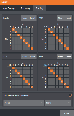
The controls in this group determine output routing of the various channels supplied as inputs to the various output mix busses (MASTER, AUX 1, etc.).
Busses and Outputs
Advanced mixers often provide more than one send for individual inputs. For example, the sound from all inputs may be sent to the master bus, comprising the master mix. A different mix, sometimes called a sub-mix, might also be created by sending certain signals to a secondary (auxiliary, or Aux) bus.
Tip: A secondary mix, prepared on an Aux bus, can serve many purposes. For example, you might wish to record a mix with all sound from talent microphones but that excludes any sound effects or music.
The Audio Mixer provides four primary audio busses. These are identified in the Audio Mixer as:
-
Master
-
AUX 1, 2 and 3
The Audio Mixer provides controls for each of these busses, allowing you to manage levels and signal processing. It is important to understand the distinction between busses and outputs.
An output may be physical, or virtual (it may involve a connector on the rear panel, or not). For example, audio recorded internally does not require an output connector. Likewise, it may initially be analog or digital.
Note: Analog outputs 1 and 2 are permanently assigned to Master and AUX 1, respectively. In contrast, digital (or embedded) outputs are configurable in the Output Configuration panel.
Sub-Mixes and Mix Minus
Specialized sub-mixes of this sort are often referred to as mix-minus, since one or more sources are deliberately subtracted from the mix. Mix-minus capabilities can be invaluable for productions like phone-in shows.
This eliminates annoying echoing, feedback and the like. Also important, independent control and signal processing is provided for each part of the pipeline.
Mix Minus for External Audio Devices
The Routing tab provides 8x8 matrix routing panels for each input, allowing for more sophisticated mixes than the example above. Viz Vectar Plus supports eight channel NDI output, so it is possible to route a unique mono mix-minus on each of these channels for an Aux bus. Thus, a single NDI a/v output stream can provide all of the mix-minus needed for up to eight external callers.
For example, if you configured Switcher inputs 13-16 to receive audio from four unique remote callers, video MIX 2 can be used to supply Program video to each caller (if the equipment supports video return). AUX 1 is configured as the Audio source for MIX 2, then assign a unique (mono) mix minus to four of its channels to supply return audio for each caller.
-
In the Output Configuration panel, assign Aux 1 as the Audio source for MIX 2.
-
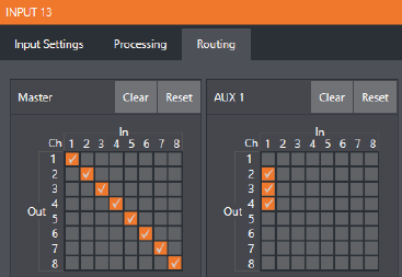
In the Audio Mixer, open the audio configuration pane for Input 13.
-
Access the Routing tab and click the Clear button above the Aux 1 routing matrix.
-
Check channels 2, 3 and 4 in the column below In 1. This routes sound from the first incoming caller to all Aux 1 output channels except channel 1.
-
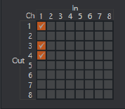
Open the audio configuration pane Input 14 and, in the Routing tab, clear the Aux 1 matrix.
-
Check channels 1, 3 and 4 in the column below In 1. This routes sound from the second incoming Skype caller to all Aux 1 output channels except channel 2.
-
Repeat the steps above for audio inputs 15 and 16, omitting the Aux 1 checkmarks under In 1 for channels 3 and 4, respectively.
This is a mix minus configuration for return to four callers, using a single NDI output.
Supplemental Audio Devices
Viz Vectar Plus features two additional menus provided at the bottom of the Routing tab, in panel Supplemental Audio Device.
This menu lists any additional devices detected by the system. Viz Vectar Plus' support for ASIO drivers allows you to easily transmit or receive audio using these popular audio over IP protocols. For example, transmit channels from Audinate’s Dante network audio protocol is listed here if you have installed Dante Virtual Sound Card software. Any audio connections on the motherboard are also listed here.
Making a selection results in the sound from source being sent to the corresponding audio channels of the designated output. You can, for example, send your Media Player output to an external hardware mixer supporting the same protocol, and route that mixer’s out back into your Vizrt system for output with your video.
Note: Apart from the AUX and Master mixes, routing or mixing is not applied to supplemental outputs. Each source channel is mapped to the corresponding output channel in 1:1 fashion, limited by the number of channels the output driver supports (for example, a stereo output always transmits channels 1 and 2 from the source).