
Viz Engine Administrator Guide
Version 5.0 | Published December 20, 2022 ©
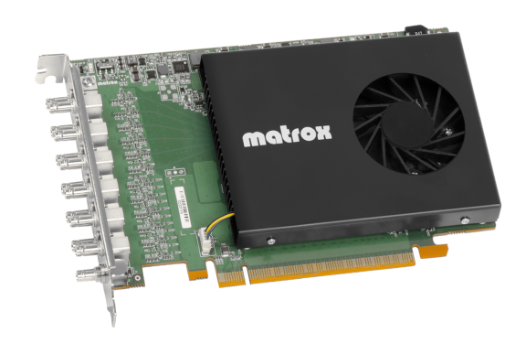
Matrox X.mio5 SDI
The Matrox X.mio5 12G video board, similar to the X.mio3 12G, is also targeted for the growing UHD market. It is a half-length, full height PCI Express card that offers up to four 12G SDI inputs and up to four 12G SDI outputs, as well as four additional 3G SDI channels, which can be freely configurable as input or output channels. The card is based on the original Matrox X.mio3 design and is capable of handling multiple combinations of 12G or 3G fill/key input and output streams.
Important: Due to the increased bandwidth of the signal, it is important to use high quality cables and as few connection points as possible. It is not recommended to use converter cables from Mini-BNC to standard BNC.
Key Features
-
Versatile 12G and quad 3G SDI for UHD connectivity.
-
Up to 4x 12G inputs and 4x 12G outputs with 4x 3G reconfigurable I/O.
-
Up to 12x completely reconfigurable 3G I/O connectors.
General Notes
-
Matrox X.mio5 12G does not support the watchdog functionality any more.
-
SD formats are not supported on Matrox X.mio5 12G.
-
AES/EBU audio is not supported on Matrox X.mio5 12G.
-
The 12G channels can of course be used as 3G channels, including quad 3G SDI for UHD resolutions.
Matrox X.mio5 12G Configuration
The main video properties match those of a Matrox X.mio3 or X.mio5 IP, but for the 12G flavor it is now possible to configure the multiconnector mode when performing quad 3G SDI for UHD. Please see Matrox Configuration for further details.
Changing Connectors Mapping
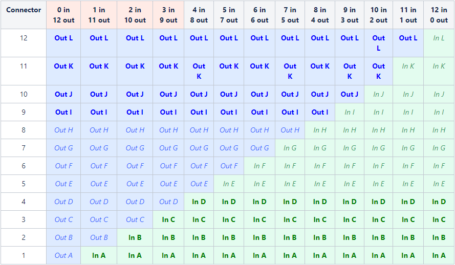
The I/O configuration of the X.mio5 12G card can have up to 13 different flavors concerning the number and types of input and output channels, according to the table below ( 12G output channels , 3G output channels , 12G input channels , 3G input channels ).
To change the connectors mapping, first ensure that no topology is currently created in the card (no Viz Engine instance is using this card, otherwise the update process will fail).
The I/O configuration can be changed using a read-only configuration file located in the folder Xmio5Le5ConnectorMapping where the Matrox drivers are installed (normally under C:\Program Files\Matrox DSX-TopologyUtils\drivers) and involves basically two steps:
-
From the drivers folder that contains mvConnectorConfig.exe, open the command prompt (administrator privileges are requested).
-
Call mvConnectorConfig.exe load -f="C:\path\to\file.pin" -sn=Axxxxxx. Replace Axxxxxx with the serial number of the card you want to configure. Pin files for different numbers of inputs and outputs are located in the Xmio5Le5ConnectorMapping\Xmio5 sub folder. Provide the full path, within quotation marks, to the desired file. Using relative paths does not work and can flash the card to an invalid status. If this happens, flash the card again with the absolute path.
Example: To configure the card with serial number A123456 to use the first four connectors as inputs and the other eight as outputs, use the command: mvConnectorConfig.exe Load -f="C:\Program Files\Matrox DSX-TopologyUtils\drivers\Xmio5Le5ConnectorMapping\Xmio5\xmio5_x2_04i08o.pin" -sn=A123456
Information: there are two configuration "families" or groups. One consists of the first four flavors in the table above (second to fifth columns: from 0 in, 12 out to 3 in, 9 out) and the other one with all other flavors (the other columns: from 4 in, 8 out to 12 in, 0 out). When changing between configurations inside the same configuration family/group, the command should take one to two seconds to process the new configuration and a restart of the computer is not needed.
When the change of configuration involves going from one configuration family to the other, this will take some time, since a firmware upgrade takes place (empirically five to ten minutes) and it requires a system restart (command line waits for user input on whether the restart should happen now or not).
Availability of Channels in Viz Engine
All configured channels are explicitly available for direct usage in Viz Engine when HD resolutions are used. However, when the system is configured to UHD (or only the specific channel) some availability rules apply.
For UHD, we can only use 12G channels (input channels A, B, C and D; output channels I, J, K, L) or quad 3G channels. Viz Engine only allows quad 3G configurations on channels A, E and I (both for inputs and outputs). Thus in UHD mode, all other channels won't be explicitly available, but simply managed internally and automatically. So as an example, it might be that we have six outputs and six inputs configured. In UHD mode, only the last four output channels are available, since the first two are 3G ones and have no usage. Analogously, only the first four input channels are available in this case.
When a given channel is configured as quad 3G, Viz Engine automatically uses the next three. For example, if channel A was chosen, it is the first one in the set and B, C and D are automatically used. Same for E (F, G, H) and I (J, K, L).
Concerning alpha channels, the easy rule is "Fill A Key B", "Fill C Key D", and so on, also for both input and output channels. The same applies for UHD in 12G channels. When using quad 3G channels, there is not a lot possibilities. So if Fill uses [A,B,C,D] than Key automatically uses [E,F,G,H], assuming these channels are available, or if Fill uses [E,F,G,H], than Key automatically picks [I,J,K,L].