
Viz Engine Administrator Guide
Version 5.0 | Published December 20, 2022 ©
Matrox X.mio3 IP / DSX LE 4 IP
The Matrox X.mio3 IP video board was designed to help broadcast equipment manufacturers meet the challenges of the SDI to IP transition. It is a half-height, half-length PCIe card that offers multi-channel video I/O over 10 GbE with IP encapsulation of HD and 3G video. The card offers a total of four IP inputs and four IP outputs. The stream content conforms either to the SMPTE 2022-6 or the SMPTE ST 2110 specification. SMPTE ST 2022-7 is supported in both modes.
DSX LE 4 IP cards have the same capabilities as their X.mio3 counterparts, but lack an onboard video mixer, so DVE is not usable on those boards. Whenever X.mio3 IP is mentioned in this document, the same is true for DSX LE 4 IP.
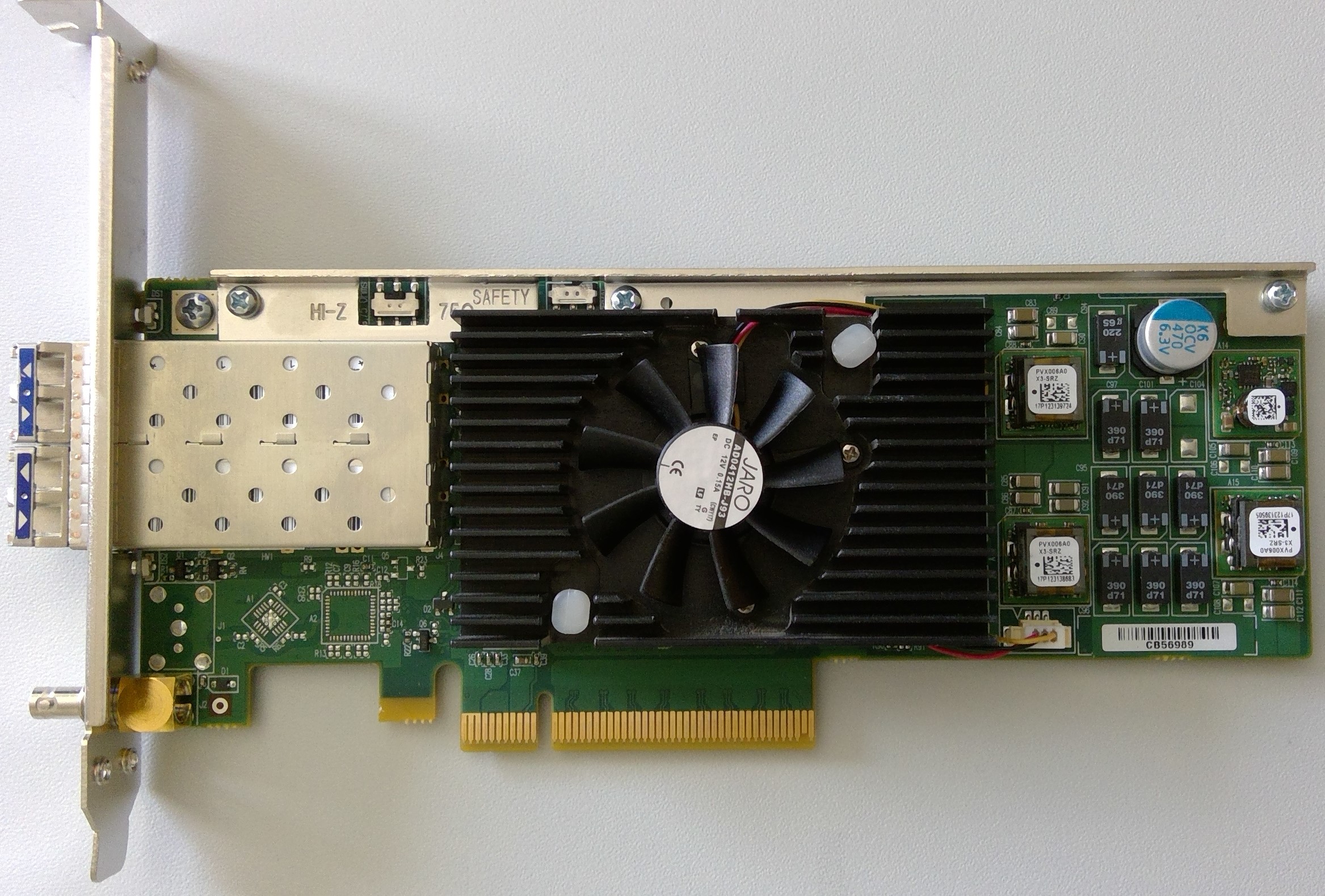
The card contains two enhanced small form-factor pluggable (SFP+) slots, or "bays". In the lower bay is SFP A, and hosts input and output channels 1 through 4. The upper bay houses SFP B, which hosts all of the redundant channels used with SMPTE ST 2022-7. The board does not have any SDI inputs or outputs. There is one Mini-BNC connector used to connect the card to the house genlock signal. However, the card can also be locked to a SMPTE ST 2059 conform time signal, sent via the SFPs.
Be aware that SFPs come in two flavors:
-
Short range (SR, 850 nm), and
-
Long range (LR, 1310 nm).
In general, a cable may only connect two SFPs of the same type. In addition, please be aware that the SFP should not be constantly switched in and out of the X.mio3 IP card, as the warranty on the card may be voided if this occurs more than 40 times.
Key Features
-
Dual SFP+ cages for a total of four video inputs and four video outputs
-
IP (SMPTE ST 2059 PTP) and analog blackburst timing reference
-
Guaranteed non-bursty packet transmission
-
Onboard multi-channel Up/Down/Cross scaler
-
Onboard multi-layer compositor
Matrox X.mio3 IP Configuration and IP Properties
The main video properties of the IP input channels are very similar to live input channels on a Matrox card. These properties are accessible in the Video Input: Live Input section of Viz Configuration.
Fill and Key Channel Mapping
When an output channel uses the alpha channel, a key channel is created. This is always the next numbered output channel:
-
Fill is on output 1, and key is on output 2.
-
Fill is on output 3, and key is on output 4.
Note: It is possible for a dual channel setup to use independent output channels on one SFP, for example 1 and 2. In this case, the Use alpha property must be disabled for both channels.
Default IP Properties
The default IP configuration is meant to serve as placeholder only. It is required to change those default values to match your internal IP landscape. All IP related settings were moved to a separate configuration file. To get the file, Viz Engine must be started at least once. After that, the configuration can be changed using the commands mentioned below, or by editing the file ipconfig.xml, located in the ProgramData directory of Viz Engine. The manual step is necessary for all settings not linked to a command. Please refer to the section below for further information.
Configuration Settings
The configuration of the IP settings was moved to an XML file containing IP relevant parameters only.
Note: When editing the XML file, do not delete any tags and only edit values between <tag> and </tag>.
SFP Settings
|
Setting |
Description |
|
IPv4Address |
Indicates the static IPv4 address. |
|
IPV4Gateway |
Indicates the IPv4 Gateway. |
|
IPv4Netmask |
Indicates the IPv4 Netmask. |
|
Smpte2059SfpSettings::TypeOfServiceDSCP |
Indicates that the Type of Service (ToS) is Differentiated Service Code Point (DSCP). |
|
Smpte2059SfpSettings::DelayMechanism |
Indicates the type of delay mechanism to use for the time server connection. |
|
Smpte2059SfpSettings::IpMode |
Indicates the type of internet protocol mode to use for the time server connection. |
|
Smpte2059SfpSettings::MasterClockDomainNumber |
Indicates the time server clock domain number to use. |
|
Smpte2059SfpSettings::JoinType |
Indicates the type of membership request made. |
|
Smpte2059SfpSettings::IgmpV3Settings::FilterType |
Only needed when the join type is set to 3 = IGMPv3. Indicates the filter type applied. |
|
Smpte2059SfpSettings::IgmpV3Settings::FilterListCount |
Indicates the number of IPv4 source addresses in the filter list. Maximum is four. |
|
Smpte2059SfpSettings::IgmpV3Settings::FilterList |
Indicates the list of IPv4 source addresses to filter separated by commas. |
General Output Settings for SMPTE ST 2022-6 and SMPTE ST 2110
|
Setting |
Description |
|
Redundancy |
If set to true, enables the redundant stream for seamless reconstruction conforming to SMPTE ST 2022-7. |
Video Output Settings for SMPTE ST 2022-6 and SMPTE ST 2110
|
Setting |
Description |
|
RtpPayloadId |
For SMPTE ST 2110 only: Indicates the RTP (Real-time Transfer Protocol) payload ID. |
|
TimeToLive |
Indicates the time in which packets can be used in seconds. That is, it indicates the packets' Time to live (TTL). |
|
TypeOfServiceDSCP |
Indicates that the Type of Service (ToS) is Differentiated Service Code Point (DSCP). |
|
TypeOfServiceECN |
Indicates that the Type of Service (ToS) is Explicit Congestion Notification (ECN). |
|
Primary::SrcUdpPort |
Indicates the User Datagram Protocol (UDP) port of the sender (that is, transmitter). |
|
Primary::DstAddress |
Indicates the IPv4 address of the destination (that is, receiver). Only used in multicast. |
|
Primary::DstUdpPort |
Indicates the UDP port of the destination (that is, receiver). |
|
Secondary::SrcUdpPort |
Indicates the redundant stream UDP port of the sender (that is, transmitter). |
|
Secondary::DstAddress |
Indicates the redundant stream IPv4 address of the destination (that is, receiver). Only used in multicast. |
|
Secondary::DstUdpPort |
Indicates the redundant stream UDP port of the destination (that is, receiver). |
Audio Output Settings for SMPTE ST 2110 only
|
Setting |
Description |
|
RtpPayloadId |
Indicates the RTP (Real-time Transfer Protocol) payload ID. |
|
TimeToLive |
Indicates the time in which packets can be used in seconds. That is, it indicates the packets' Time to live (TTL). |
|
TypeOfServiceDSCP |
Indicates that the Type of Service (ToS) is Differentiated Service Code Point (DSCP). |
|
TypeOfServiceECN |
Indicates that the Type of Service (ToS) is Explicit Congestion Notification (ECN). |
|
AudioPacketDuration |
Indicates the outgoing audio packet duration. |
|
Primary::SrcUdpPort |
Indicates the User Datagram Protocol (UDP) port of the sender (that is, transmitter). |
|
Primary::DstAddress |
Indicates the IPv4 address of the destination (that is, receiver). Only used in multicast. |
|
Primary::DstUdpPort |
Indicates the UDP port of the destination (that is, receiver). |
|
Secondary::SrcUdpPort |
Indicates the redundant stream UDP port of the sender (that is, transmitter). |
|
Secondary::DstAddress |
Indicates the redundant stream IPv4 address of the destination (that is, receiver). Only used in multicast. |
|
Secondary::DstUdpPort |
Indicates the redundant stream UDP port of the destination (that is, receiver). |
Ancillary Data Output Settings for SMPTE ST 2110 only
|
Setting |
Description |
|
RtpPayloadId |
Indicates the RTP (Real-time Transfer Protocol) payload ID. |
|
TimeToLive |
Indicates the time in which packets can be used in seconds. That is, it indicates the packets' Time to live (TTL). |
|
TypeOfServiceDSCP |
Indicates that the Type of Service (ToS) is Differentiated Service Code Point (DSCP). |
|
TypeOfServiceECN |
Indicates that the Type of Service (ToS) is Explicit Congestion Notification (ECN). |
|
SMPTE352Payload |
If set to 1, enables SMPTE 352 packets. |
|
Primary::SrcUdpPort |
Indicates the User Datagram Protocol (UDP) port of the sender (that is, transmitter). |
|
Primary::DstAddress |
Indicates the IPv4 address of the destination (that is, receiver). Only used in multicast. |
|
Primary::DstUdpPort |
Indicates the UDP port of the destination (that is, receiver). |
|
Secondary::SrcUdpPort |
Indicates the redundant stream UDP port of the sender (that is, transmitter). |
|
Secondary::DstAddress |
Indicates the redundant stream IPv4 address of the destination (that is, receiver). Only used in multicast. |
|
Secondary::DstUdpPort |
Indicates the redundant stream UDP port of the destination (that is, receiver). |
General Input Settings for SMPTE ST 2022-6 and SMPTE ST 2110
|
Setting |
Description |
|
Redundancy |
If set to true, enables the redundant stream for seamless reconstruction conforming to SMPTE ST 2022-7. |
|
JoinType |
Indicates the type of membership request made. |
Video Input Settings for SMPTE ST 2022-6 and SMPTE ST 2110
|
Setting |
Description |
|
RtpPayloadId |
For SMPTE ST 2110 only: Indicates the RTP (Real-time Transfer Protocol) payload ID. |
|
Primary::DstAddress |
Indicates the reception multicast IPv4 address. |
|
Primary::DstUdpPort |
Indicates the reception User Datagram Protocol (UDP) port. |
|
Primary::PacketIntervalThreshold |
Indicates the threshold for generating the time interval between the IP packets alarm on the video flow. |
|
Primary::IgmpV3Settings::FilterType |
Only needed when the join type is set to 3 = IGMPv3. Indicates the filter type applied. |
|
Primary::IgmpV3Settings::FilterListCount |
Indicates the number of IPv4 source addresses in the filter list. Maximum is four. |
|
Primary::IgmpV3Settings::FilterList |
Indicates the list of IPv4 source addresses to filter separated by commas. |
|
Secondary::DstAddress |
Indicates the redundant stream reception multicast IPv4 address. |
|
Secondary::DstUdpPort |
Indicates the redundant stream reception UDP port. |
|
Secondary::PacketIntervalThreshold |
Indicates the threshold for generating the time interval between the IP packets alarm on thevideo flow. |
|
Secondary::IgmpV3Settings::FilterType |
Only needed when the join type is set to 3 = IGMPv3. Indicates the filter type applied. |
|
Secondary::IgmpV3Settings::FilterListCount |
Indicates the number of IPv4 source addresses in the filter list. Maximum is four. |
|
Secondary::IgmpV3Settings::FilterList |
Indicates the list of IPv4 source addresses to filter separated by commas. |
Audio Output Settings for SMPTE ST 2110 only
|
Setting |
Description |
|
RtpPayloadId |
For SMPTE ST 2110 only: Indicates the RTP (Real-time Transfer Protocol) payload ID. |
|
AudioPacketDuration |
Indicates the outgoing audio packet duration. |
|
Primary::DstAddress |
Indicates the reception multicast IPv4 address. |
|
Primary::DstUdpPort |
Indicates the reception User Datagram Protocol (UDP) port. |
|
Primary::PacketIntervalThreshold |
Indicates the threshold for generating the time interval between the IP packets alarm on the audio flow. |
|
Primary::IgmpV3Settings::FilterType |
Only needed when the join type is set to 3 = IGMPv3. Indicates the filter type applied. |
|
Primary::IgmpV3Settings::FilterListCount |
Indicates the number of IPv4 source addresses in the filter list. Maximum is four. |
|
Primary::IgmpV3Settings::FilterList |
Indicates the list of IPv4 source addresses to filter separated by commas. |
|
Secondary::DstAddress |
Indicates the redundant stream reception multicast IPv4 address. |
|
Secondary::DstUdpPort |
Indicates the redundant stream reception UDP port. |
|
Secondary::PacketIntervalThreshold |
Indicates the threshold for generating the time interval between the IP packets alarm on the audio flow. |
|
Secondary::IgmpV3Settings::FilterType |
Only needed when the join type is set to 3 = IGMPv3. Indicates the filter type applied. |
Ancillary Data Output Settings for SMPTE ST 2110 only
|
Setting |
Description |
|
RtpPayloadId |
For SMPTE ST 2110 only: Indicates the RTP (Real-time Transfer Protocol) payload ID. |
|
Primary::DstAddress |
Indicates the reception multicast IPv4 address. |
|
Primary::DstUdpPort |
Indicates the reception User Datagram Protocol (UDP) port. |
|
Primary::PacketIntervalThreshold |
Indicates the threshold for generating the time interval between the IP packets alarm on the ancillary data flow. |
|
Primary::IgmpV3Settings::FilterType |
Only needed when the join type is set to 3 = IGMPv3. Indicates the filter type applied. |
|
Primary::IgmpV3Settings::FilterListCount |
Indicates the number of IPv4 source addresses in the filter list. Maximum is four. |
|
Primary::IgmpV3Settings::FilterList |
Indicates the list of IPv4 source addresses to filter separated by commas. |
|
Secondary::DstAddress |
Indicates the redundant stream reception multicast IPv4 address. |
|
Secondary::DstUdpPort |
Indicates the redundant stream reception UDP port. |
|
Secondary::PacketIntervalThreshold |
Indicates the threshold for generating the time interval between the IP packets alarm on the ancillary data flow. |
|
Secondary::IgmpV3Settings::FilterType |
Only needed when the join type is set to 3 = IGMPv3. Indicates the filter type applied. |
Change IP Properties
Although the IP properties may be changed by editing the configuration file directly, the IP address and port numbers can also be set via the command line interface. Because channel numbering is zero-based here, Output Channel 1 is referred to as VIDEOOUT_0. To check the currently configured values call the command using GET (instead of SET) without parameters.
To Change/Check the Destination Address and Port of the Output Channels:
For SMPTE ST 2022-6/-7 and SMPTE ST 2110:MAIN*CONFIGURATION*MATROX*VIDEOOUT_x*DSTADDRESS SET xxx.xxx.xxx.xxxMAIN*CONFIGURATION*MATROX*VIDEOOUT_x*DSTUDPPORT SET xxxxxMAIN*CONFIGURATION*MATROX*VIDEOOUT_x*REDUNDANCYDSTADDRESS SET xxx.xxx.xxx.xxxMAIN*CONFIGURATION*MATROX*VIDEOOUT_x*REDUNDANCYDSTUDPPORT SET xxxxxFor SMPTE ST 2110 only:MAIN*CONFIGURATION*MATROX*VIDEOOUT_x*DSTADDRESSAUDIO SET xxx.xxx.xxx.xxxMAIN*CONFIGURATION*MATROX*VIDEOOUT_x*DSTUDPPORTAUDIO SET xxxxxMAIN*CONFIGURATION*MATROX*VIDEOOUT_x*REDUNDANCYDSTADDRESSAUDIO SET xxx.xxx.xxx.xxxMAIN*CONFIGURATION*MATROX*VIDEOOUT_x*REDUNDANCYDSTUDPPORTAUDIO SET xxxxxMAIN*CONFIGURATION*MATROX*VIDEOOUT_x*DSTADDRESSANC SET xxx.xxx.xxx.xxxMAIN*CONFIGURATION*MATROX*VIDEOOUT_x*DSTUDPPORTANC SET xxxxxMAIN*CONFIGURATION*MATROX*VIDEOOUT_x*REDUNDANCYDSTADDRESSANC SET xxx.xxx.xxx.xxxMAIN*CONFIGURATION*MATROX*VIDEOOUT_x*REDUNDANCYDSTUDPPORTANC SET xxxxxTo Change the Source Address of the Input Channels:
For SMPTE ST 2022-6/-7 and SMPTE ST 2110:MAIN*CONFIGURATION*CHANNELS*LIVEIN_x*DSTADDRESS SET xxx.xxx.xxx.xxxMAIN*CONFIGURATION*CHANNELS*LIVEIN_x*DSTUDPPORT SET xxxxxMAIN*CONFIGURATION*CHANNELS*LIVEIN_x*REDUNDANCYDSTADDRESS SET xxx.xxx.xxx.xxxMAIN*CONFIGURATION*CHANNELS*LIVEIN_x*REDUNDANCYDSTUDPPORT SET xxxxxFor SMPTE ST 2110 only:MAIN*CONFIGURATION*CHANNELS*LIVEIN_x*DSTADDRESSAUDIO SET xxx.xxx.xxx.xxxMAIN*CONFIGURATION*CHANNELS*LIVEIN_x*DSTUDPPORTAUDIO SET xxxxxMAIN*CONFIGURATION*CHANNELS*LIVEIN_x*REDUNDANCYDSTADDRESSAUDIO SET xxx.xxx.xxx.xxxMAIN*CONFIGURATION*CHANNELS*LIVEIN_x*REDUNDANCYDSTUDPPORTAUDIO SET xxxxxMAIN*CONFIGURATION*CHANNELS*LIVEIN_x*DSTADDRESSANC SET xxx.xxx.xxx.xxxMAIN*CONFIGURATION*CHANNELS*LIVEIN_x*DSTUDPPORTANC SET xxxxxMAIN*CONFIGURATION*CHANNELS*LIVEIN_x*REDUNDANCYDSTADDRESSANC SET xxx.xxx.xxx.xxxMAIN*CONFIGURATION*CHANNELS*LIVEIN_x*REDUNDANCYDSTUDPPORTANC SET xxxxxX.mio3 IP Command Examples
Set the source address of input channel 4. Because channel numbering is zero-based here, IP Input Channel 4 is referred to as LIVEIN_3.
MAIN*CONFIGURATION*CHANNELS*LIVEIN_3*DSTADDRESS SET 224.10.10.34Set the source UPD port of input channel 4:
MAIN*CONFIGURATION*CHANNELS*LIVEIN_3*DSTUDPPORT SET 9004Query the destination properties of output 1, fill
> MAIN*CONFIGURATION*MATROX*VIDEOOUT_0*DSTADDRESS GET < 224.10.10.102 > MAIN*CONFIGURATION*MATROX*VIDEOOUT_0*DSTUDPPORT GET < 20000Query the destination properties of the key channel associated with output 1:
> MAIN*CONFIGURATION*MATROX*VIDEOOUT_1*DSTADDRESS GET < 224.10.10.104 > MAIN*CONFIGURATION*MATROX*VIDEOOUT_1*DSTUDPPORT GET < 20000