Viz Engine Administrator Guide
Version 5.0 | Published December 20, 2022 ©
Matrox
In the Matrox section, assign Matrox Input and Output channels to Viz Engine Input and Output channels. The GUI shows a drop down menu for the configurable parameters. The parameters available are dependent on the installed hardware.
This page provides information about the following:
General Properties
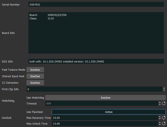
The General Properties Panel shows information about the installed hardware.
-
Serial No.: Shows the serial number of the installed Matrox board.
-
Board Info: Shows the model and type of the Matrox board.
-
DSX Info: Shows the software version and driver version.
-
Fast Texture Mode: Activate to shorten the ’in out’ delay in Texture Mode to a minimum.
Note: If Fast Texture Mode is set to Active, DVE does not work (see Video Clip Playout Considerations and Video Playout in the Viz Artist User Guide).
-
Shared Input Host:
-
CC Extraction: Enables or disables the closed captioning extraction for Matrox X.mio3 / DSX LE 4.
-
Print Clip Info: Enables printing of clip information to the console when activated. However, such information may cause the render loop to stall. Default mode is Inactive.
-
Watchdog: Sets a timer that allows a system to continue video pass-through during an application crash or system failure (see also Matrox Watchdog Configuration (Matrox X.mio Series) and Video Board):
-
Use Watchdog: When set to Active enables the Matrox X.mio watchdog feature. It passes the input signal to a hardcoded output port as soon as Viz Engine is unresponsive. Default mode is Inactive.
-
Timeout: Sets the time, in milliseconds, until the watchdog takes over control. This value should not be smaller than the time of two fields/frames. Default value is 999 ms.
Note: Use Watchdog and Timeout can also be set and changed in Video Board.
-
-
Genlock:
-
Use Flywheel: Adopts a tracking mode if the genlock signal is interrupted or lost that maintains the signal frequency until the source genlock signal is regained when activated. Default mode is Active.
-
Max Recovery Time: Represents the time in milliseconds (ms) provided to the flywheel to attempt to regain the genlock before an abrupt jump to the locked state is performed. Default value is 15.
-
Max Unclock Time: Represents the time in milliseconds (ms) provided to the flywheel to remain in the unlocked state before switching to the free running state. Default value is 15.
-
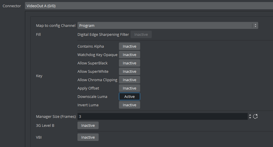
VideoOut Properties
In the VideoOut panel, you select which Viz Artist/Engine Output is mapped to the selected Matrox output. The VideoOut panel shows the mapped Viz output channel and its editable parameters. When your video input is set to UHD in the Video Input section of the config menu (see Video Input: Live Input), Matrox channels B, C and D are disabled.
Map to Config Channel
-
Map to config Channel: Selects which video out channel is mapped to the selected Matrox video out channel. Select an Output channel from the drop-down menu. Only channels not already in use are shown. On single channel configurations, VideoOut A is usually mapped to Program, and VideoOut B to Preview. On dual Channel configurations, the first channel maps VideoOut A to Program, and the second maps VideoOut B to Program.
-
Unused: Does not map this Matrox channel for output.
-
Program: Maps the Program output to the selected video output of the Matrox card.
-
Preview: Maps the Preview output to the selected video output of the Matrox card.
-
Clean: Outputs video without overlay graphics. Clean mode enables and activates a second output feed. This feed consists of DVE video content without any graphics and video textures: only live video, clip video, IP input, streaming input. This stream also includes a separate audio mix corresponding to the video only, excluding stage audio such as audio clips, plug-in audio or text-to-speech, from the clean feed audio mix. If Watchdog functionality is required, VideoOut A must be mapped to Clean, and VideoOut B to Program. Requires Matrox X.mio3, X.mio3 IP, or DSX LE4.
-
Downscaled Preview: Outputs a downscaled to HD version of the Program output. This channel is only initialized if the Program output is configured to UHD. It has the same video content of Program, but is downscaled to HD. Otherwise, this channel is ignored by Viz Engine.
Note: A clean feed increases the video In->Out delay by one frame!
-
Fill Properties
-
Digital Edge Sharpening Filter: Applies an edge sharpening filter to digital output video. Default mode is Inactive. SD configurations only.
Key Properties
-
Contains Alpha: Defines if this output channel provides key information on the associated key output connector.
-
Watchdog Key Opaque: Specifies if the output key must be opaque or transparent when the watchdog unit activates. Default mode is Inactive.
-
Allow Super Black: Determines whether to clip an output video signal that is under 7.5 IRE units. Default mode is Inactive.
-
Allow Super White: Determines whether to clip an output video signal that is over 100 IRE units. Default mode is Inactive.
Note: Please see the description about allowing Super White and Super Black in the Fill Properties section above.
-
Allow Chroma Clipping: Determines whether to clip over-saturated chroma levels in the active portion of the output video signal. Default mode is Inactive.
-
Apply Offset: Applies an offset to the luminance values such that the inverted result still falls within the 16-235 range. Default mode is Inactive.
-
Downscale Luma: Compresses the luminance range of the output key signal from 0-255 to 16-235. Default mode is Active.
-
Invert Luma: Inverts the luminance part of the output key signal (inverts the key). Default mode is Inactive.
Multiconnector Mode
Defines which multiconnector mode to use for 3G / 12G SDI channels. This setting is only available for Series 5 Matrox SDI cards (for example, Xmio5 12G SDI) when configured to UHD.
-
None: 12G single connector mode.
-
2SI: Quad-Link 2 sample interleave.
-
Square Division: Quad-Link Square division.
Manager, Repeat and 3G Properties
-
Manager Size (frames): Sets the number of frames available in the on-board memory for output. A too high value may cause memory problems on the Matrox board. Default value is 3.
-
3G Level B: Activates Level B for 3G mode in 1080p 50/60/60M (default mode is Level A).
VBI Properties
Use this switch to enable or disable VBI (Vertical Blanking Interval) in the output.
M264 Encoder/Decoder Boards
M264 encoder/decoder boards are usually configured automatically. If they do not appear in the configuration section, please double check the Matrox.Devices entry in the MATROX_CONFIG of the viz.cfg file.
It should look like Matrox.Devices = <device1>,<device2>.
Depending on your model(for example, a M264 S3, which supports three streams), the entry would look like: Matrox.Devices = <device1>,<m264device>,<m264device>,<m264device>.