
Viz Engine Administrator Guide
Version 5.0 | Published December 20, 2022 ©
Matrox X.mio3 / DSX LE 4
This section first gives an overview of the Matrox X.mio3 video cards, then describes the details specific to the full height X.mio3 FH and low profile X.mio3 LP versions of the card. The Matrox X.mio3 IP / DSX LE 4 IP board is discussed in a separate section.
DSX LE 4 cards have the same capabilities as their X.mio3 counterparts, but lack an onboard video mixer, so DVE is not usable on those boards. Whenever X.mio3 is mentioned in this document, the same is true for DSX.LE 4.

In this section:
Matrox X.mio3 Overview
The X.mio3 can be ordered in two configurations: FH (full height, 12 physical HD-BNC connectors, plus one connector for sync) and LP (low profile, eight physical HD-BNC Connectors, plus one connector for sync). Both are half length PCI express Gen2 x8 cards.
-
X.mio3FH (Full Height, half length) with up to 12 I/O ports, SD to 4K capable. This card can be ordered with six, eight or X2 (12) I/O. Eight ports are hardwired through relays: Four inputs to four outputs. Model /6 means six I/Os are available, model /8 eight I/Os. Model X2 (twelve ports) has four freely configurable ports. There can be maximum eight I/Os of one type (either in or out) enabled on a card.
-
X.mio3LP (Low Profile, half length) with up to eight I/O ports, SD to 4K capable.
-
The I/O ports are configurable. This means that for instance the X.mio3 model /8 can be configured to have from 8/0 (for example, 8 channels in, zero channels out) to 0/8 (zero channels in, eight channels out). Only even combinations are allowed.
-
One connector is reserved for a reference signal (sync) marked as REF.
The default card is an X.mio3/6/100, meaning X.mio3 FH with six connectors class 100. The class 100 can not play any video clips and upgrade to class 500 is required to enable both SD and HD clip playback. For Apple ProRes support, the class 550 is needed.
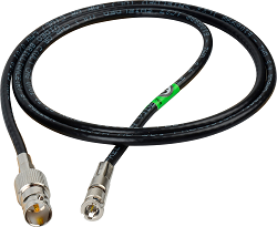
The I/O connectors for the X.mio3 are of the Mini-BNC (also called HD-BNC) type. The use of cable converters from Mini-BNC to BNC may be required.
The X.mio3 cards can be combined with the AES Audio Kit for 16 AES audio channels In/Out, see X.mio3 AES Audio Kit.
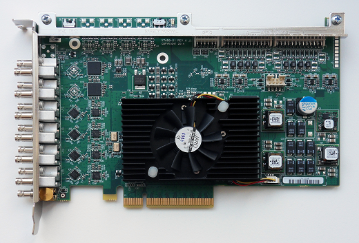
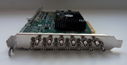
X.mio3 FH
X.mio3 FH provides multichannel SDI IO with hardware based video processing in a full-height, half-length PCI express card with 13 physical HD-BNC connectors. This card provides up to 12 reconfigurable I/Os, from SD to 4K, one connector is reserved for sync. Support for AES/EBU, LTC and GPIO provide for versatile connectivity. The multi-channel hardware processing accelerates compute-intensive operations including motion-adaptive de-interlacing, up/down/cross scaling and mixing/compositing for all resolutions, including 4K.
Key Features
-
Half-length PCI express card
-
Re-configurable IO that can support up to 12 SDI IO
-
Frame synchronizers
-
VANC and HANC support for each input and output
-
Analog black burst reference input (tri-level or bi-level)
-
On-board multi-channel MADI (Motion Adaptive De-Interlacer)
-
On-board multi-channel Up/Down/Cross scaler
-
On-board multilayer compositor
-
Automatic video relay bypass
-
Live zero-frame delay video and audio mixers
-
Up to 16 channels of AES/EBU inputs and outputs
-
Up to eight LTC inputs and outputs
-
RS422 control
-
Single slot all inclusive option
IMPORTANT! Not all X.mio3 hardware features are supported by Viz Engine. Features available depends on drivers, SDK and Engine versions in use.
X.mio3 LP
Matrox X.mio3 LP is a low-profile, half-length PCIe card with up to eight reconfigurable SDI I/Os from SD to 4K.
Key Features
-
Low profile, half-length PCI-e card.
-
Re-configurable I/O that can support up to eight SDI inputs or outputs.
-
Frame synchronizers.
-
VANC and HANC support for each input and output.
-
Analog black burst reference input (tri-level or bi-level).
-
On-board multi-channel MADI (Motion Adaptive De-Interlacer).
-
On-board multi-channel Up/Down/Cross scaler.
-
On-board multilayer compositor.
-
Automatic video relay bypass (optional).
-
Live zero-frame delay video and audio mixer.
IMPORTANT! Not all X.mio3 hardware features are supported by Viz Engine. Features available depends on drivers, SDK and Engine versions in use.
The X.mio3 LP models are: /4, /6, /8 - corresponding to the number of I/O port the configuration supports.
X.mio3 Connector Mapping Reference
This section is a reference for X.mio3 connector mappings.
Upgrades and firmware setup of I/O mapping should be done by Vizrt or a qualified technician.
The X.mio3 connectors are labeled 1 through 12 (plus one connector for sync), eight connectors for the LP (low profile) card. As explained, the connectors can be configured for in or out and with various capabilities for clip playback depending on class - with possibilities for firmware class upgrades.
IMPORTANT! There can be maximum eight ports of the same type (either in or out), this restriction also applies to the model x2 that has 12 connectors.
Connectors 1,3,5,7 are always reserved for input, connectors 2,4,6,8 for output. Hence, if the Watchdog is active port 1 (in) goes to port 2 (out) with relay, port 3 (in) to port 4(out) and so on.
The x2 model can as mentioned only have eight I/Os of the same type; 8in - 4out or 4in - 8out.
To configure the X.mio3 card for usage:
-
Make sure that the card has the required mix of inputs and outputs required for the intended usage, for instance to satisfy fill, key, full-screen graphics requirements. This is done, if required, with the mvConnectorConfig.exe utility described in X.mio3 I/O Port Configuration.
-
Map the I/Os from step 1 above to the Viz Video channels using the Viz Engine Configuration utility. This is mostly the same procedure for X.mio3 as for previous Matrox cards, see Viz Engine Matrox Video Mapping Configuration.
FH X.mio3 X2 Connector Mapping for Quad-Link Inputs
The following table lists the connectors used for quad-link inputs, depending on the I/O port mapping of the card. This has been tested on X.mio3 X2 and approved by QA. It may differ from card to card. Viz Engine does not support fill+key for quad-link inputs and the mapping between Engine input channels and ports is hard-coded.
|
FPGA configuration |
Mapping |
Input |
Connectors used |
Connectors used |
|
2SI |
4in/8out |
1 |
A-C-E-G |
1-3-5-7 |
|
8in/4out |
1 |
A-C-I-J |
1-3-9-10 |
|
|
2 |
E-G-K-L |
5-7-11-12 |
||
|
Square Division (SD) |
4in/8out |
1 |
A-C-E-G |
1-3-5-7 |
|
8in/4out |
1 |
A-C-E-G |
1-3-5-7 |
|
|
2 |
I-J-K-L |
9-10-11-12 |
X.mio3 I/O Port Configuration
Normally the I/O ports are pre-configured when delivered from Vizrt. If the I/O configuration needs to be changed, the Matrox command-line utility mvConnectorConfig.exe normally found in:
C:\Program Files\Matrox DSX-TopologyUtils\drivers\mvConnectorConfig.exemust be used. mvConnectorConfig.exe can be called from the command prompt without options to get a helpful usage message. To configure all X.mio3 cards in a system to use four inputs and two outputs the syntax is:
C:\Program Files\Matrox DSX-TopologyUtils\drivers\mvConnectorConfig.exe -4in2outTo configure six outputs and no inputs the syntax is:
C:\Program Files\Matrox DSX-TopologyUtils\drivers\mvConnectorConfig.exe -0in6outand so on for the various I/O possibilities.
The computer should be stable with low load and no Viz programs running when using the configuration utility. Never interrupt a firmware upgrade. After making changes to the Matrox I/O configuration, the computer must be re-started with a complete power off.
Note: Only even combinations are supported (for example, an eight connector board can be configured as 80, 62, 44, 26 or 08).
Viz Engine Matrox Video Mapping Configuration
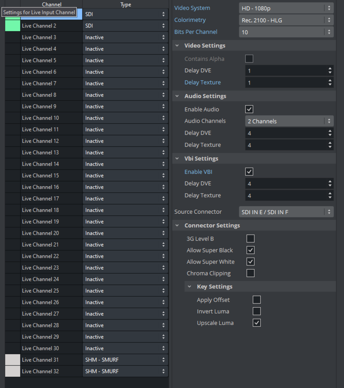
Open Viz Configuration > Matrox to configure the Matrox video channel mapping and mapping type.
The Viz video inputs are named alphabetically and limited to the number of available I/O channels the system has. The number in parenthesis indicates which channel is being used for fill and key. If you do not need a key signal in the output, de-select the Key > Contains Alpha option to make the I/O channel available for other usages. Example configuration:
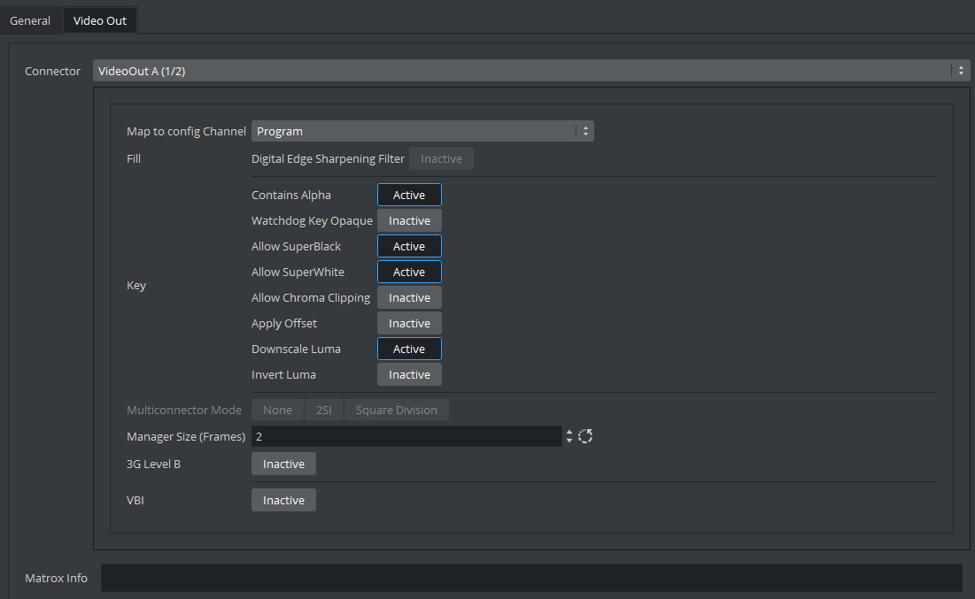
Navigate to Config > Matrox > Video Out for an overview showing which I/O channels are used for fill and key:
To Upgrade X.mio Class and Firmware
To upgrade your X.mio3 card, for example to enable more IO-ports or a codec upgrade for HD-Clipback, you must use the mvDongleUpdater.exe update utility with your Vizrt supplied license upgrade file <filename>.OPT. This utility is installed with the Matrox driver package and is normally installed to:
C:\Program Files\Programs\Matrox DSK.utils\drivers\mvDongleUpdater.exe To upgrade the card use this syntax:
C:\Program Files\Matrox DSX.utils\drivers\mvDongleUpdater.exe upgrade -sn="SerialNumberofthecard" -f="Path to the upgrade file" The command above must be run from a Windows command line window (WINDOWS BUTTON > cmd > ENTER).
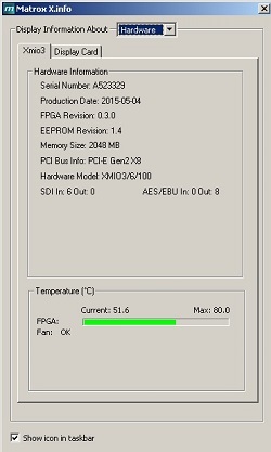
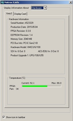
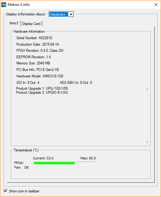
The Matrox X.info utility is used to display information about the card class, how the Input and Outputs are configured, serial number and more. This utility can normally be started from the Windows taskbar. A typical information window would be:
X.mio3 AES Audio Kit
|
X.mio3 Class 100 |
X.mio3 Class 550 |
|
|
|
The X.mio3 AES Audio Kit connects to the X.mio3 card internally and takes up one slot as indicated in the picture below:
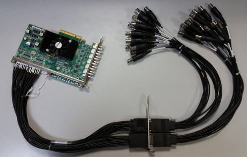
The kit contains:
-
Two internal cables with bracket.
-
Two external cables, each cable has:
-
Eight AES/EBU in and eight AES/EBU out (total 16 AES/EBU in and out).
-
Four LTC in and four LTC out (total eight LTC in and out).
-
Upgrading Matrox Firmware for 2 Sample Interleave
To make your card capable of 2 SI UHD:
-
Check if you have an X.mio3 X2 series SDI card.
-
Flash the firmware. Open a command line and run the following command:
Flashing X2 cardcd C:\Program Files\Matrox DSX.utils\driversmvConnectorConfig.exe -2SI=on -
Restart the machine.
-
Check X.Info, which should state that the card is now in 2SI mode.
Refer to the connector mapping in the section above for 2SI, 2SI alternate connector mapping.