
Viz Artist User Guide
Version 5.1 | Published October 31, 2023 ©
Projected Virtual Window
Prerequisites
Tracking
Make sure Tracking Hub is set up properly and the Engine receives the correct tracking data, since tracking data is mandatory for a proper virtual window representation.
Getting Started
To create a projected Virtual Window, at least two scenes are necessary. The first one contains the actual content of the scenery outside the Virtual Window, the second one contains a virtual representation of the video walls position and its dimensions in the actual studio.
Content Scene
The content scene can be anything, best practices creating a set for a Virtual Studio apply. The content scene is used within a GFX Channel, so keep that in mind as well when designing the scene.
Camera Settings
Configuration
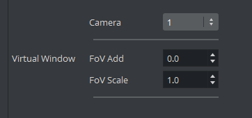
When the content scene is being rendered with the tracking data's Field of View, it happens that the virtual window gets cut off too early when moving the real camera. To mitigate that problem, FoV Add and FoV Scale can be adjusted for each remote camera in the Engine's Camera configuration:
-
FoV Add: Degrees added to the incoming Field of View.
-
FoV Scale: Factor the incoming Field of View is multiplied with.
Both values can be changed on the fly, no restart of the Engine is needed. Make sure to save the configuration after changing the values.
Scene
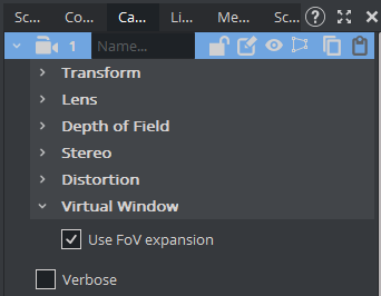
Additionally to configuring those values, it is necessary to enable their usage within the scene's camera by ticking Use FoV expansion.
FoV Calculation
The final FoV that is being used for rendering is: FoV(final) = FoV(Tracking) * FoV_Scale + FoV_Add.
Playout Scene
The playout scene needs a virtual representation of your Video Wall in the form of a geometry and the Virtual Window plug-in. It is crucial to know the exact placement and dimensions of the video walls relative to the origin of your virtual studio (tracking data).
Virtual Window Plug-in

The Virtual Window plug-in is responsible to render your virtual window geometry and generate the output. It is supported by both the Viz Engine Render Pipeline and the Classic Render Pipeline. The usage is a bit different depending on the selected pipeline.
Settings
Screen
The screen settings define the area where your virtual window is rendered on the final Viz Engine output. This allows to define the region of the screen that is used to render the virtual window content. It defines the flat 2D region which represents either a whole video wall (X/Y = 0.0 Width/Height = 100.0) or just a part of it when multiple windows are needed within a single Viz Engine output (for example when a curved or tiled wall is used in the studio). It ultimately makes it possible to use more than one Virtual Window plug-in from within a single scene and drive multiple virtual windows with a single setup.
-
Position: The position of the rectangle in percentages of the output resolution.
-
Dimension: The dimension of the rectangle in percentages of the output resolution.
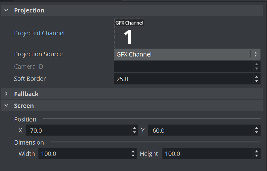
Projection
The projection settings are responsible to link the content to the output scene.
-
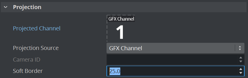
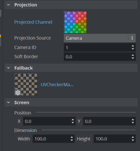
Projected Channel (Viz Engine Renderer only): Slot where the GFX Channel that renders the content scene must be added to.
-
Projection Source: The virtual window plug-in needs to know camera settings the content was rendered with. GFX Channel automatically reads the data from the assigned GFX Channel, Camera allows to specify a camera via Camera ID.
-
Camera ID: The camera number from 1-16 where the plug-in reads camera the data from. Only valid when Projection Source is set to Camera.
-
Soft Border: Adds a fade effect on the borders of the projected window.
Fallback
-
Fallback Texture: Any image that can be used as a fallback shown outside view frustum:
Multi Panel Plug-in

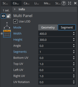
The Multi Panel plug-in is a geometry plug-in that helps create the virtual representation of the video wall setup. It allows to create multiple different shapes from rectangular to curved ones. The plug-in contains the actual video walls dimensions and its alignment in the real studio.
This plug-in can create multiple segments within the same geometry, easily allows it to have rotated tiles seamlessly merged together if the dimension of the tiles are the same (symmetrical video wall setup).
Settings
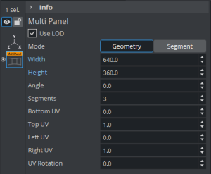
Mode: Defines how the properties are being used to generate the video wall geometry:
|
|
Geometry |
Segment |
|
Width |
Width of the geometry in cm. |
Width of a single segment in cm. |
|
Height |
Height of the geometry in cm. |
Height of a single segment in cm. |
|
Angle |
Rotation angle around Y-axis in degrees. |
Angle in degrees between 2 consecutive shapes. |
|
Segments |
Number of subdivisions. |
Number of consecutive segments. |
|
Bottom UV |
UV coordinate for the lower edge where y = 0. |
UV coordinate for the lower edge where y = 0. |
|
Top UV |
UV coordinate for the upper edge where y = Height. |
UV coordinate for the upper edge where y = Height. |
|
Left UV |
UV coordinate for the left edge where x = 0. |
UV coordinate for the left edge where x = 0. |
|
Right UV |
UV coordinate for the right edge where x = Width. |
UV coordinate for the rightmost edge where x = Width * Segments. |
|
UV Rotation |
Rotation Angle around the UV center. |
Rotation Angle around the UV center. |
Setup Guide
Engine
-
Start with the Video Wall configuration.
-
Enable Tracking Hub and make sure you are receiving the tracking data.
-
Configure the Virtual Window FoV Add, set it to 5 for the tracked cameras as a start.
-
Render scale must be 1.0.
-
Distortion and Parameter mode needs to be setup correctly for the cameras as well. Most likely it is Internal / Tracking Hub.
Content Scene
-
Start with the set you want to use as content.
-
Cameras need to be set to Remote.
-
Enable the Use FoV Expansion Flag on the remote cameras.
-
Save the scene and close it.
Playout Scene
-
Start with an empty scene (or any scene you use for playout and want to modify).
-
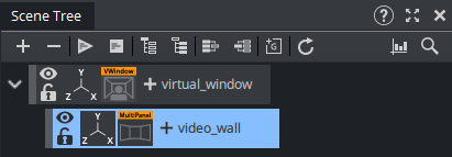
Add a container with Virtual Window plug-in (virtual_window).
-
Add a sub-container with the Multi-Panel plug-in (video_wall).
-
Add a GFX Channel as Texture, set the Scene.
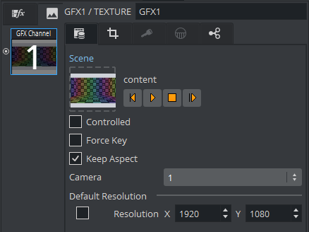
-
Make sure the GFX Channel's Camera is set to the camera that is tracked. Don't use Auto or Main Scene, because the Playout scene most likely uses a different camera.
-
Manually set the Resolution of the GFX Channel. This should match the resolution of your real camera, most likely HD.
-
Select the Virtual Window plug-in.
-
Set the content scene's GFX Channel to Projected Channel.
-
Set the Projection Source to GFX Channel.
-
Select the Container with the Multi Panel plug-in and configure the video wall geometry (position, translation) according the real worlds videowall.
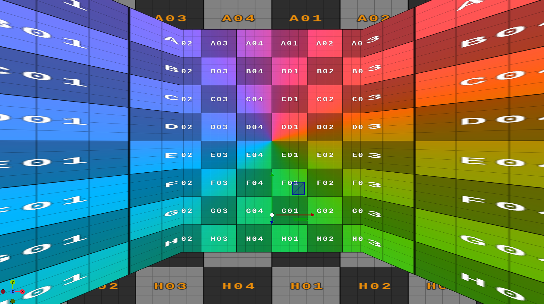
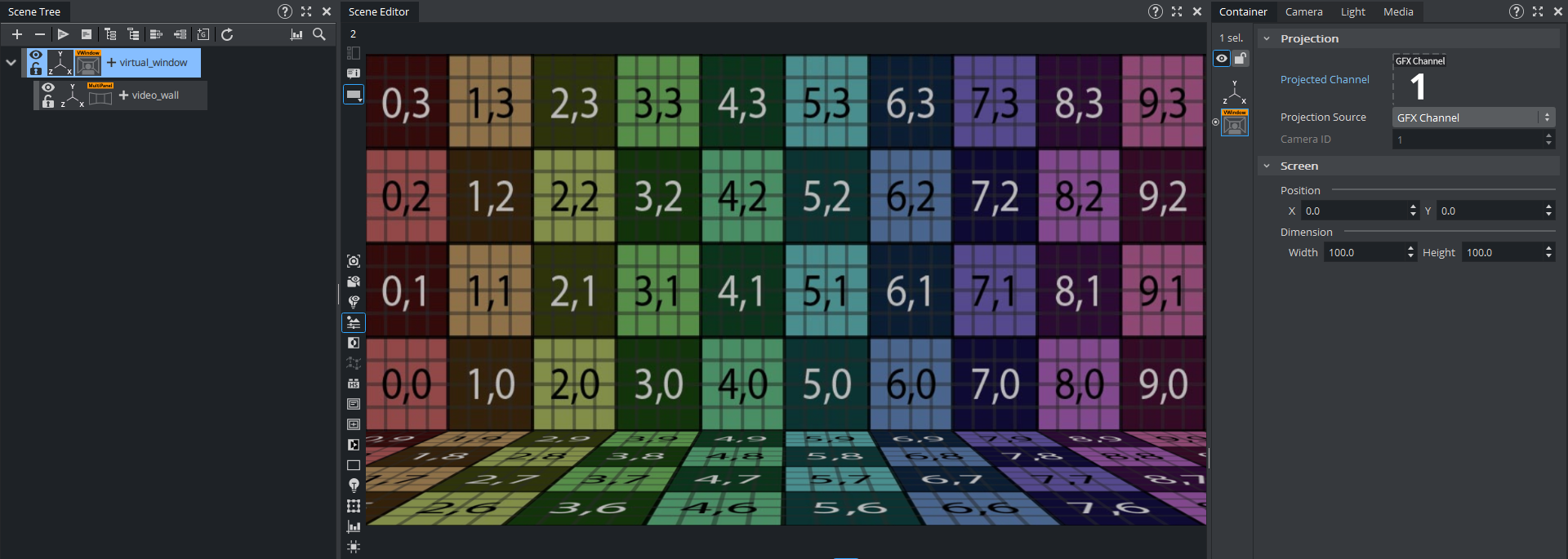
Scene Editor
The final rendering behavior is only done when the Post Processing Effects are enabled.
Post Processing Off
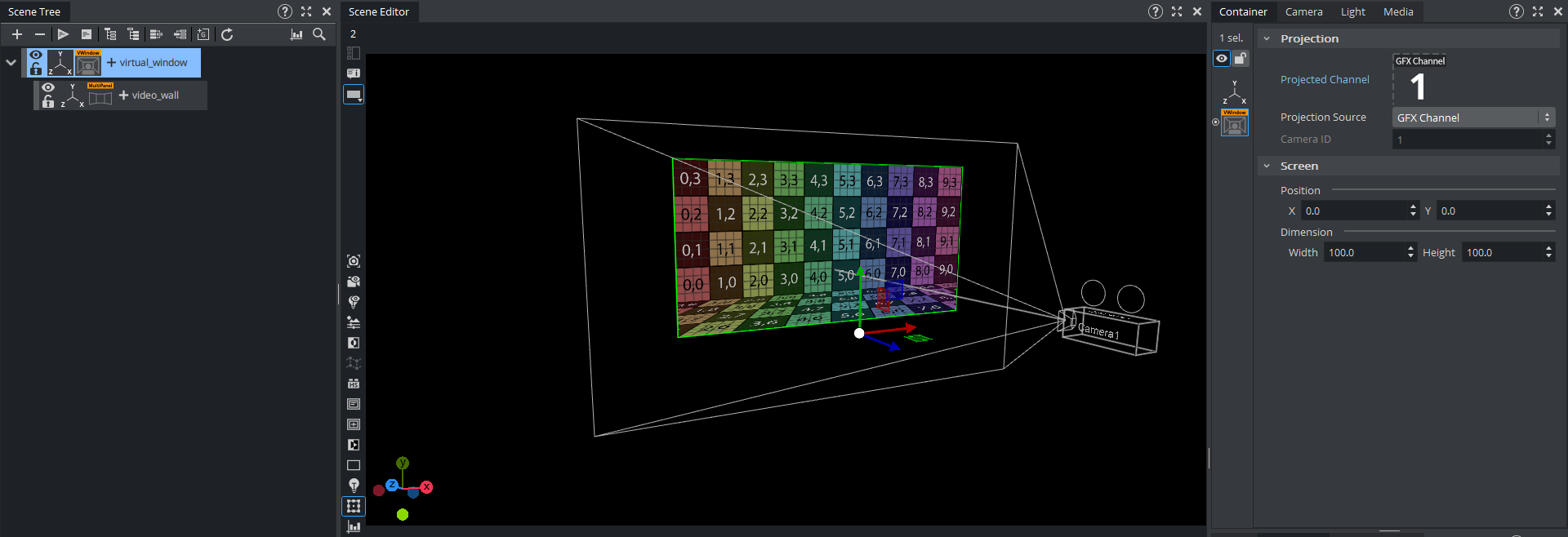
Post Processing On
Setup Scenarios
Scenario 1: Single Tile Video Wall
The single tile video wall is showing the virtual window on the whole output from, meaning the Virtual Window plug-in is set to Position X/Y = 0.0 on full scale (Width/Height = 100.0)
The multi panel plug-in contains only one segment, having the physicals video wall dimensions for height and width set.
In case a rotation angle is needed, the actual containers translation parameters can be adjusted to fit the geometry in 3D space.
Scenario 2: Multiple Symmetrical Tiles Video Wall or Curved Video Walls
If the real videowall consists of multiple tiles which share the same dimensions a single Multi Panel plug-in, it can handle the whole wall setup. This also can be used when working on curved videowalls where the curved gets interpreted by creating multiple rotated tiles stitched together.
Example A: Three Tiled Wall
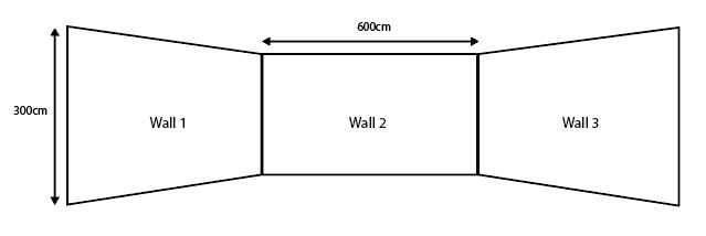
This example has three physical video wall segments in the studio which have the same size of 600cm x 300cm.
The setup within the playout scene can be done by using one Videowall plug-in in combination with the Multi Panel plug-in containing three segments, rotated 45 degrees to each other.
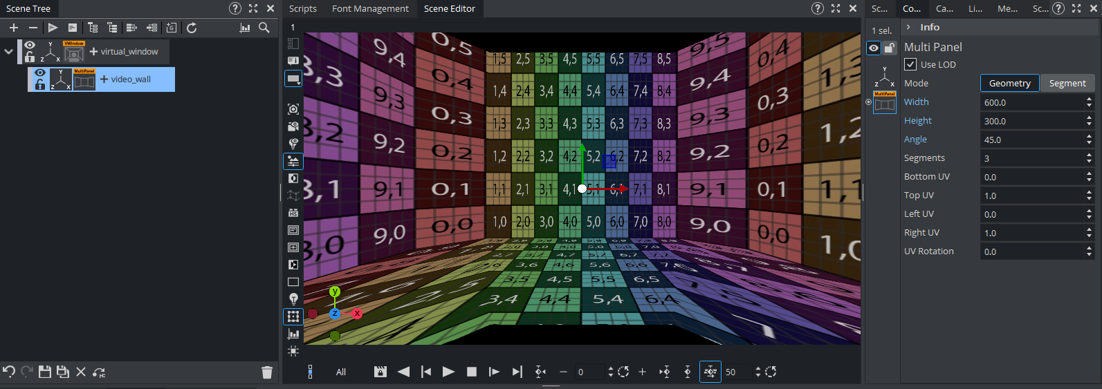
In this scenario the Multi Panel plug-in is set to geometry mode, containing of three subdivisions having the same dimensions.
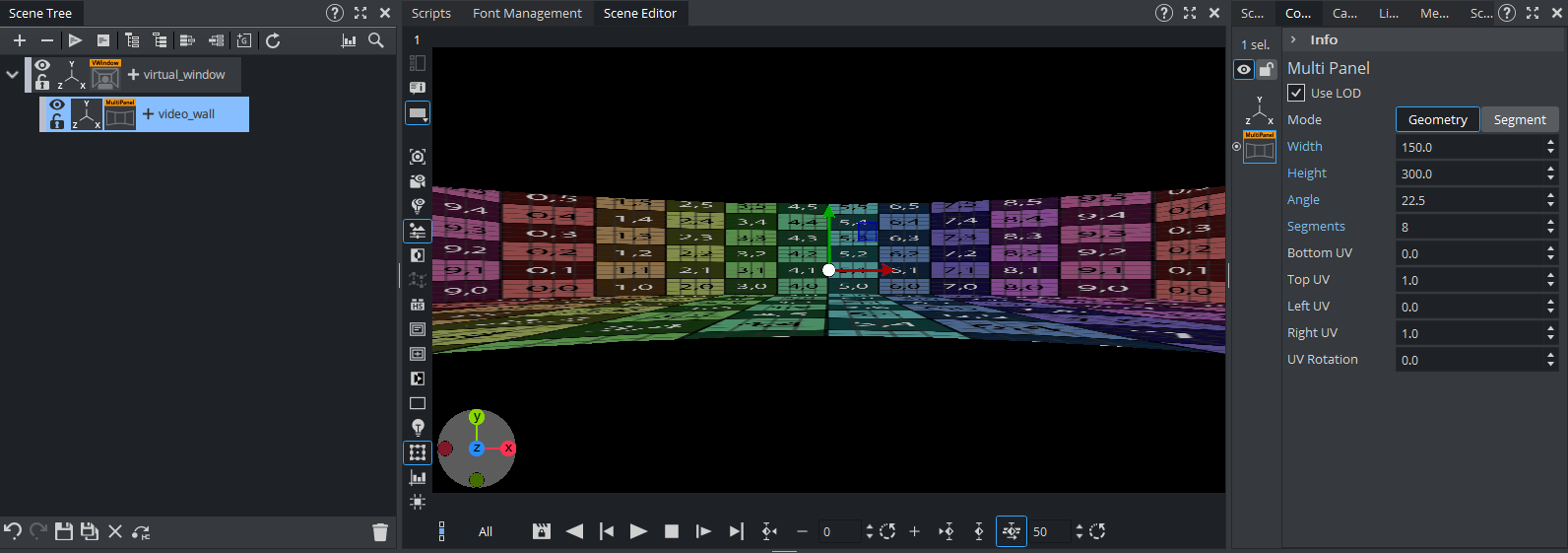
Example B: 180 Degree Curved Wall
In order to simulate a curved wall, the amount of divisions within the Multi Panel plug-in needs to be increased to have a more realistic looking output on the real wall.
For a 180 degree curved wall using eight subdivisions should be sufficient.
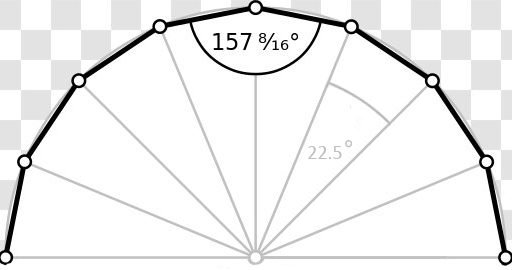
Depending on the size of the real videowall the division dimensions need to be calculated accordingly. This example has each division set to a width of 150cm by keeping the height of 300cm.
Note: These screenshots are taken by disabling the remote camera feature for explanation purposes. The correct output can only be properly seen when using a remote camera.
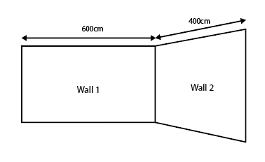
Scenario 3 - Non-symmetrical Video Wall
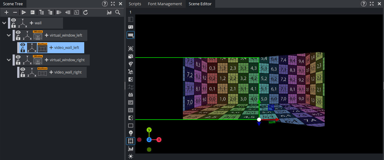
A typical video wall setup can contain two walls having different dimensions. In this case, the setup needs to have two virtual windows set up in the scene tree.
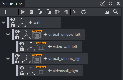
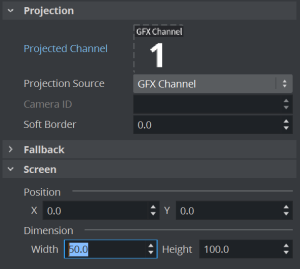
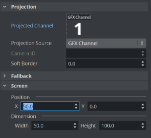
In this case, each of the Virtual Window plug-ins need to be resized to only match 50% of the Viz Engine output. This depends on how the overall Nvidia Mosaic or the videowalls image processor is configured. Typically having this is set up by assuming this is a split 50-50 screen setup.
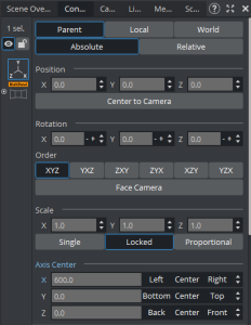
Setup of the plug-ins (left / right):
Now each virtual window gets a Multi Panel plug-in assigned, containing the real dimension of the corresponding physical wall in the studio. Using a non-symmetrical setup is done by choosing the Segment mode inside the Multi Panel plug-in.

As soon as the dimension of the walls are set, the containers/geometries can be placed correctly in the 3D world. This of course has to be done according to its real position in the studio. All measurements have to be done related to the real studios Zero Point (point of reference).
Turning off the Post Effect view in Artist, helps to easily adjust the containers position.
Rearranging the containers Axis center helps it to stitch both geometries together seamlessly. In this example the left wall has its axis center set to right, the right wall is set to left while both container have set their position to X = 0, which makes them touch each other directly on the studios zero point.
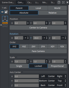
Since the right wall also has an angle, this can easily be added within the containers translation properties. The angle within the Multi Panel plug-in does not have to be adjusted.
This example has the left wall rotated for 30 degrees:
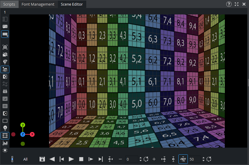
The actual Viz Engine output (show the post effects) now projects two walls each using 50% of the screen. Depending on the cameras angle within the tracked content scene, the two walls with adapt while still being stitched together seamlessly in the center.
Unreal Engine
Content Scene
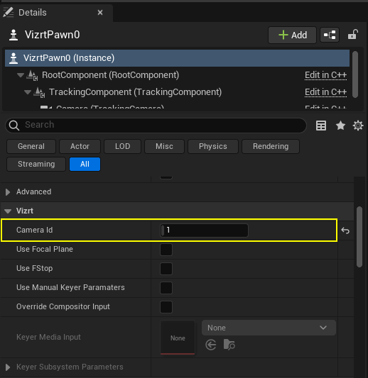
Follow the Unreal Engine guide to setup a Viz Virtual Studio scene without the compositor. The VizrtPawn's camera number needs to be set to the one receiving the tracking data:
Playout Scene
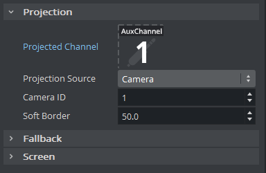
The setup of the playout scene is the same as using Viz Engine native content, except that the Virtual Window plug-in needs to use the AuxChannel instead of GfxChannel. In addition it is necessary to change the Projection Source to Camera and the Camera ID needs to be set to the one receiving the tracking data as well.
Warning: It is crucial to have the camera rendering delay configured correctly, otherwise there will be jitter on the videowall when moving the camera.