Object Tracker User Guide
Version 1.1 | Published November 15, 2022 ©
Viz Scene Design
This section describes how to design a scene to be used with the object tracker.
Live Video Input
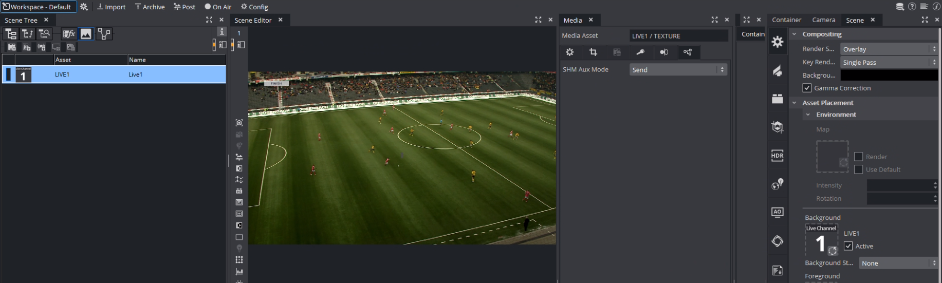
The most important setting of a scene that can be used with the Object Tracker is the live input. The SHM Aux Mode must be set to Send. This allows the Object Tracker to read the input surface from the Engine. The Live Input asset needs to be present in the scene but does not necessarily need to be visible, so the result can be still composed on an external mixer.
It is possible to use other texture source such as clip channels. You need to make sure that the SHM Aux Mode is set to Send and that the configured Input Key (see Configuration > Tracking in the Viz Arc User Guide) matches the SHMAuxKey configuration of the Object Tracker's Viz Engine (for example, viz_clip1_aux, viz_live1_aux, etc.).
Container Scripts
![]()
Main Tracking Script
As the tracking data comes into Viz Engine through shared memory, these values need to be read and translated into screen coordinates. This can happen through a script:
dim MapName as Stringdim screenWidth as Doubledim screenHeight as Doubledim mpi = 3.14159265359dim degToRad = mpi/180.0sub OnInit() MapName = GetParameterString("mapName") 'do some trigonometry to get the screen width/height on the 0 plane. 'this calculation works in orto and perspective mode but the camera needs 'to look straight down the z axis (no rotation). Works well with the 'default camera settings screenWidth = tan(scene.CurrentCamera.Fovx*0.5*degToRad)*scene.CurrentCamera.Position.z*2 screenHeight = tan(scene.CurrentCamera.Fovy*0.5*degToRad)*scene.CurrentCamera.Position.z*2end subsub OnExecPerField() Dim bbTarget = GetParameterContainer("bbTarget") Dim centerTarget = GetParameterContainer("centerTarget") Dim visibilityTarget = GetParameterContainer("visibilityTarget") dim pos as Vertex dim bbHeight as Double dim bbWidth as Double dim quality as Double dim zActive as Boolean pos.x = VizCommunication.Map[MapName&"PX"] pos.y = VizCommunication.Map[MapName&"PY"] pos.z = VizCommunication.Map[MapName&"PZ"] bbWidth = VizCommunication.Map[MapName&"RY"] bbHeight = VizCommunication.Map[MapName&"RX"] quality = VizCommunication.Map[MapName&"RZ"] zActive = cBool(pos.z == 1) 'println zActive & " " & pos.x if( visibilityTarget.Active == false AND zActive == true) Then visibilityTarget.Active = true this.Active = true Println "ACTIVATE GFX +++++++++++++++++" end if if( visibilityTarget.Active == true AND zActive == false) Then visibilityTarget.Active = false this.Active = false Println "DEACTIVATE GFX +++++++++++++++++" end if if visibilityTarget.Active == true then centerTarget.position.x = pos.x*screenWidth centerTarget.position.y = -pos.y*screenHeight findSubContainer("quality").GetFunctionPluginInstance("ControlNum").SetParameterString("input", cStr(quality*100.0)) bbTarget.position.x = pos.x*screenWidth bbTarget.position.y = -pos.y*screenHeight bbTarget.Scaling.x = bbWidth*screenWidth/100 bbTarget.Scaling.y = bbHeight*screenHeight/100 end ifend subsub OnInitParameters() RegisterParameterString("mapName", "Map Name", "tracking1", 20,200, "") RegisterParameterContainer("bbTarget", "BB Target") RegisterParameterContainer("centerTarget", "Center Target") RegisterParameterContainer("visibilityTarget", "Visibility Target")end subsub OnParameterChanged(parameterName As String) MapName = GetParameterString("mapName")end sub ![]()
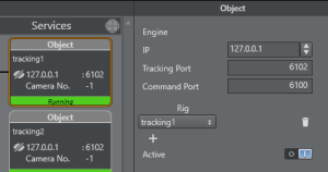
In a first step, the script calculates in the OnInit method the available width and height of the viewport on the zero Z plane. In the OnExecPerField method, the tracking data is read out using a given shared memory key (set through the Map Name parameter, default is tracking1). The name of the key must match the name of the Rig selected in the Tracking Hub's Object Service.
The script then switches on and off the target container defined in the Visibility Target parameter when tracking begins and tracking ends or is lost. This can be also replaced with a stage command for example. The parameter container Center Target is updated on every field to the actual tracking position. This is the reference point of the tracker.
Parent Transformations: The script above does not consider any parent transformations of the target container. Make sure the target container contains no additional parent transformations
The BB Target container parameter (which might contain a Noggi or Rectangle plug-in) gets resized according to the tracked width and height of the object.
Bounding Box Sizes: The bounding box sizes might become zero. This is always the case for simple and manual tracking.
Follow Bounding Box Script
Another container script can be used to position graphics in relation to the bounding box of the detected object:
Dim screenWidth as DoubleDim screenHeight as Doubledim mpi = 3.14159265359dim degToRad = mpi/180.0sub OnInit() screenWidth = tan(scene.CurrentCamera.Fovx*0.5*degToRad)*scene.CurrentCamera.Position.z*2 screenHeight = tan(scene.CurrentCamera.Fovy*0.5*degToRad)*scene.CurrentCamera.Position.z*2end subsub OnInitParameters() RegisterParameterString("mapName", "Tracker Name", "tracking1", 20,200, "") RegisterParameterContainer("ref", "Reference Container") RegisterParameterBool("followX", "Follow X", False) RegisterParameterBool("followBBX", "Follow Bounding Box Width", False) RegisterParameterDouble("deltaX", "Distance X", 0.0, -1000000, 1000000) RegisterParameterBool("followY", "Follow Y", False) RegisterParameterBool("followBBY", "Follow Bounding Box Height", False) RegisterParameterDouble("deltaY", "Distance Y", 0.0, -1000000, 1000000) RegisterParameterBool("followZ", "Follow Z", False) RegisterParameterDouble("deltaZ", "Distance Z", 0.0, -1000000, 1000000) RegisterParameterBool("doScale", "Scale by Bounding Box", False) RegisterParameterDouble("inMinScale", "Input Min Scale", 0.0, 0, 1.0) RegisterParameterDouble("inMaxScale", "Input Max Scale", 1.0, 0, 1.0) RegisterParameterDouble("minScale", "Output Min Scale", 0.0, 0, 1000000) RegisterParameterDouble("maxScale", "Output Max Scale", 1.0, 0, 1000000) end subsub OnExecPerField() Dim bbHeight as Double Dim bbWidth as Double Dim trackerName as String trackerName = GetParameterString("mapName") bbHeight = VizCommunication.Map[trackerName&"RX"] bbWidth = VizCommunication.Map[trackerName&"RY"] if GetParameterBool("followX") == true Then if(GetParameterBool("followBBX") == true) then position.X = GetParameterContainer("ref").Position.X + bbWidth * screenWidth*0.5 + GetParameterDouble("deltaX") else position.X = GetParameterContainer("ref").Position.X + GetParameterDouble("deltaX") end if end If if GetParameterBool("followY") == true Then if(GetParameterBool("followBBY") == true) then position.Y = GetParameterContainer("ref").Position.Y + bbHeight * screenHeight*0.5 + GetParameterDouble("deltaY") else position.Y = GetParameterContainer("ref").Position.Y + GetParameterDouble("deltaY") end if end If if GetParameterBool("followZ") == true Then position.Z = GetParameterContainer("ref").Position.Z + GetParameterDouble("deltaZ") end If if GetParameterBool("doScale") == true Then Dim inMin as Double Dim inMax as Double Dim outMin as Double Dim outMax as Double Dim scale = bbHeight inMin = GetParameterDouble("inMinScale") inMax = GetParameterDouble("inMaxScale") outMin = GetParameterDouble("minScale") outMax = GetParameterDouble("maxScale") scale = Max(inMin, scale) scale = Min(inMax, scale) scale = (scale-inMin)/(inMax-inMin) scale = outMin + scale*(outMax-outMin) scaling.x = scale scaling.y = scale scaling.z = scale end Ifend sub 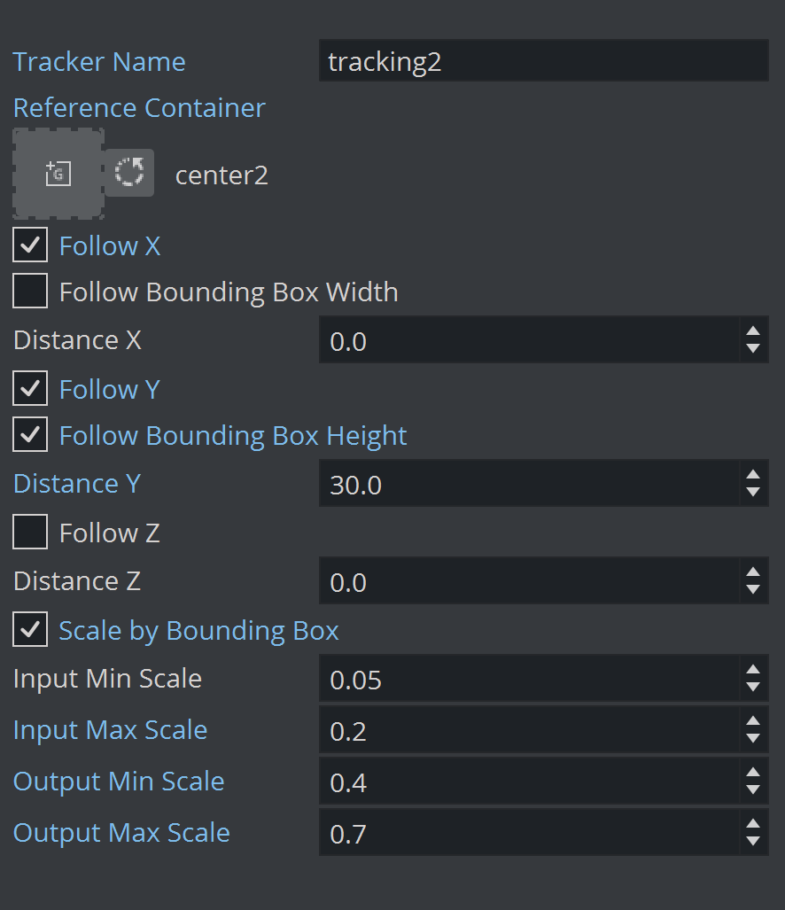
The script uses the Reference Container (that represents the tracked point), it is used very much like the Autofollow plug-in. Additionally, to follow the position of the reference container, it uses a few more parameters that determine an additional offset relative to the tracked object's bounding box.
-
Follow X: Allows the graphics follow the horizontal movement of the tracked object.
-
Follow Bounding Box Width: Positions the graphics on the right hand side of the bounding box.
-
Distance X: Adds constant horizontal offset.
-
Follow Y: Allows the graphics follow the vertical movement of the tracked object.
-
Follow Bounding Box Height: Aligns the graphics on top of the bounding box.
-
Distance Y: Adds constant vertical offset.
-
Follow Z: Unused.
-
Distance Z: Adds constant depth offset.
-
Scale by Bounding Box: Uses Bounding Box size to scale graphics.
-
Input Min Scale: Sets minimum input scale of the Bounding Box height. The input height is normalized between 0 and 1 (where 1 is the full screen height, 0.1 is 10% of the screen height etc.).
-
Input Max Scale: Sets maximum input scale of the Bounding Box height. The input height is normalized between 0 and 1 (where 1 is the full screen height, 0.1 is 10% of the screen height etc.).
-
Output Min Scale: Maps minimum output scale of the graphics.
-
Output Max Scale: Maps maximum output scale of the graphics.
Using the above sample values, a bounding box with height of 0.05 or smaller (thus 5% of the screen height or smaller) results in a scaling of 0.4 (Output Min Scale). A bounding box of height 0.2 or larger (20% or larger of the screen height) is scaled to 0.7.
All values in between 0.05 and 0.2 are interpolated linearly between 0.4 and 0.7. Adjust those values to suit your graphics. The sample in this script considers only the height of the bounding box, but it could be easily changed to consider the surface of the bounding box or the width only.