
Viz Mosart Administrator Guide
Version 4.1 | Published October 29, 2021 ©
AV Automation Devices GPIO
GPI functionality supports triggering any template from the currently active template set and including a selection of control commands.
Adding GPI/O control to a device is performed in Viz Mosart AvAutomation.
-
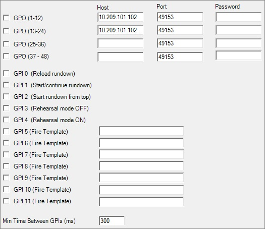
GPO (1-12): Enables a WebIO box for the first 12 GPO when checked. Note that this has to be configured for GPI 0-11 to be enabled.
-
GPO (13-24): Enables a WebIO box for the second 12 GPO when checked.
-
GPO (25-36): Enables a WebIO box for the third 12 GPO when checked.
-
GPO (37-48): Enables a WebIO box for the fourth 12 GPO when checked.
-
Host: Hostname or IP address to the WebIO GPI/O box.
-
Port: Port to communicate with the WebIO GPI/O box.
If configured as 80, Mosart will use the HTTP WebIO protocol, while for other Port values Mosart will use the Binary WebIO protocol. -
Password: Defines the password, if needed.
-
GPI 0 (check box): Enables initialize Viz Mosart rundown when the external pulse is received.
-
GPI 1 (check box): Enables start/continue the Viz Mosart timeline from an external pulse.
-
GPI 2 (check box): Enables starting Viz Mosart rundown on the first story on the external pulse.
-
GPI 3 (check box): Enables rehearsal mode off.
-
GPI 4 (check box): Enables rehearsal mode on.
-
GPI 5-11 (check boxes/custom): Enables firing of the template or command given in the text box.
Direct takes via GPI
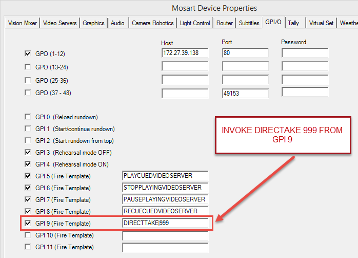
As taking a template using one of GPIs 5 to 11 (Fire Template) would add the corresponding template to the timeline, which is not always wanted, you can instead use a DIRECTTAKE control command, as explained below.
Syntax
DIRECTTAKE|<the Recall Nr of the direct take>
Example: DIRECTTAKE|99
Triggers direct take 99
Configuring
The figure below connected GPI 9 to firing direct take 999
Verifying
-
Assign a direct take to a GPI between 5 and 11
-
Restart AvA
-
Trigger this GPI from the external device connected to this GPI.
For testing this can also be done for GPIs 0 to 9 from within AvAutomation by pressing SHIFT+CTRL+<no> where <no> is the GPI number + 1 (modulo 10).
For example, SHIFT+CTRL+0 will invoke GPI 9 -
Verify on the Mosart server that the corresponding GPI is executed. One way to do this is in Av Automation, since Direct takes are shown in the Av Automation Log window (lower left) when taken.
To Trigger Direct Take Templates via a GPI
-
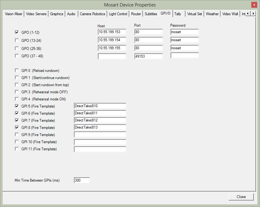
To trigger a direct take from a GPI (which can then further trigger multiple control commands) use the GPI/O tab in Av Automation > Devices > Properties as shown in the figure below.
Syntax for GPI 5-11
DIRECTTAKE|<the Recall Nr of the direct take>
Note: A GPI/GPO device must first be configured. The configuration of GPI/GPO devices is done in AV Automation Devices - GPIO.
Testing GPI signals without the use of GPI
If a GPI/GPO device is configured, as shown in the figure above, any GPI signals 0-9 may be simulated using the keyboard sequence CTRL+SHIFT+<number> inside AvAutomation to trigger a corresponding GPI.
This is an easy way to test the GPI configuration.
For example: CTRL+SHIFT+6 will trigger GPI 5
Sample Configuration (W&T Web-IO)
W&T's Web-IO products enable TCP/IP Ethernet-based switching signals for control, acquisition and monitoring. Their products are accessed using API queries from, for example, a standard web browser, or in our case, Viz Mosart.
From the Web-IO side, GPI is enabled by attaching a device capable of sending GPI signals to Viz Mosart. The configuration below shows configuration of a W&T Web-IO device capable of 24 GPI/GPO connections.
This configuration uses at a maximum 24 GPO signals. A maximum of 12 GPI signals can be used to control Viz Mosart.
GPI 0-4
The first 5 GPI signals are connected to fixed Viz Mosart commands for backward compatibility.
The signals are as follows:
GPI 0 - Reload rundown, Will trigger a rundown reload event. I.e. the timeline will be stopped and the current rundown will be reloaded from the NCS cache.
GPI 1 - Start/continue rundown. Will trigger the TAKE-NEXT event and with that start the timeline or advance to the next timeline element
GPI 2 - Start rundown from top. Will start the rundown from the first story
GPI 3 - Disable rehearsal mode
GPI 4 - Enable rehearsal mode
GPI 5-11
Each of the GPI signals 5-11 may be assigned to either trigger a Viz Mosart control command, trigger an arbitrary template from the active template set or trigger a direct take, as follows.
Triggering Mosart Control Commands
To trigger a Mosart Control Command enter a valid command in the text field associated with the GPI signal.
Supported commands:
ClearForegroundGraphics - Removes all CGs
SkipNextStory - Skips next story item
UnskipNextStory - Unskips next story item
TakeLastGraphicsOut - Removes last CG
TakeManualGraphicsOut - Removes manual CGs
PlayCuedVideoServer - Plays out the last cued clip on a video server
PausePlayingVideoServer - Pauses the currently playing clip on a video server
StopPlayingVideoServer - Stops the currently playing clip on a video server
RecueCuedVideoServer - Recues the last cued clip on a video server
Triggering a Mosart Template
This can be used to trigger a Mosart template from the active template set:
Syntax: [TemplateType]|[Variant]
-
Example: Camera|1
Triggering a Direct Take
This can be used to trigger a direct take:
Syntax: DIRECTTAKE|<the Recall Nr of the direct take>
-
Example: DIRECTTAKE|99
triggers direct take 99.
Hardware Configuration
For this example, you configure the in and out ports as required for the GPIO system, by following their own specifications.
The Web-IO physical device can be configured via a browser pointed to the box’ IP address.
-
To get into the configuration menus select
Config > Login > Administrator login
from the Start page.
Note: Configuration changes are only saved after clicking the Logout button.
Mosart IAT/SAT
-
For testing from Mosart, the new configuration is either directly loaded, or inspected and used for setting the inport 0 manually.
Inspection and comparison may be necessary should the load fail. If necessary reset the box to factory settings before using the configuration below. -
Under the inport nodes in the menu tree
-
Set the port minimum pulse filter to 100ms
-
Set the input type to positive pulse (three separate settings).
-
-
If you use port 0 it is easier to test Viz Mosart, as this port is hardwired to the Reload Rundown function.
Preparation of Test Circuit
-
This requires two pieces of wire, ~20cm, stripped (and preferably tinned) at the end.
-
To set up the box for generating an input test pulse, interconnect the terminal strip ground connector for power supply ground (the outermost VCC connector) with the outermost GND connector, across the box. This establishes a common ground between power supply side and the input logic circuits.
Note:
-
It is not possible to simply take the output of one output port and feed it directly back to the input side, as the outputs are intended to drive relay circuits (these are also known as current drivers, they operate at a very low voltage)
-
The 12 in 12 out version requires an external relay.
-
The inputs requires 8V referred to GND to detect a pulse.
-
Testing GPI 0
-
To generate the input pulse, connect a piece of wire from the other VCC connector and briefly touch the connector for Inport 0 (the pulse must be >100ms).
-
A green light beside the connector will briefly light up if successfully triggered. Given that AV Automation has GPIO enabled and is also enabled for Input 0, any loaded rundown will reload, clearly visible on the Mosart GUI.
-
Configure GPIO with the file containing the working configuration.
A sample xml file is listed in the Appendix section here.
If the GPIO will not import the configuration file directly, a workaround is to save the current configuration and using Notepad++ (or similar) to compare the difference between the new configuration and the existing configuration. Amend the configuration on the existing configuration to match the new settings.