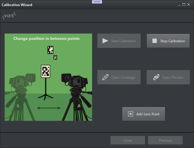
Starting the lens calibration can be achieved by either using the general lens calibration settings in the Automate Lens Calibration tab, or via the Wizard.
Automated Lens Calibration
The automated lens calibration process uses image-based calibration techniques to automatically generate a lens file. It detects targets in the incoming images, and tries to compute the target positions and lens parameters that best explain the observed images. To fit an accurate lens model, it is important to capture a wide range of zoom/focus levels.
It is important that the images used by the process do not suffer from motion blur, and that the images and the tracking data are in sync. Therefore, the camera has to stay still for a few frames before the process captures an image to use it for the calibration process.
The coverage and the preview visualizations described in the next section, guide the user through the process of capturing suitable images, ensuring an adequate coverage of the zoom/focus space, as well as input images and tracking data of sufficient quality.
Lens Coverage
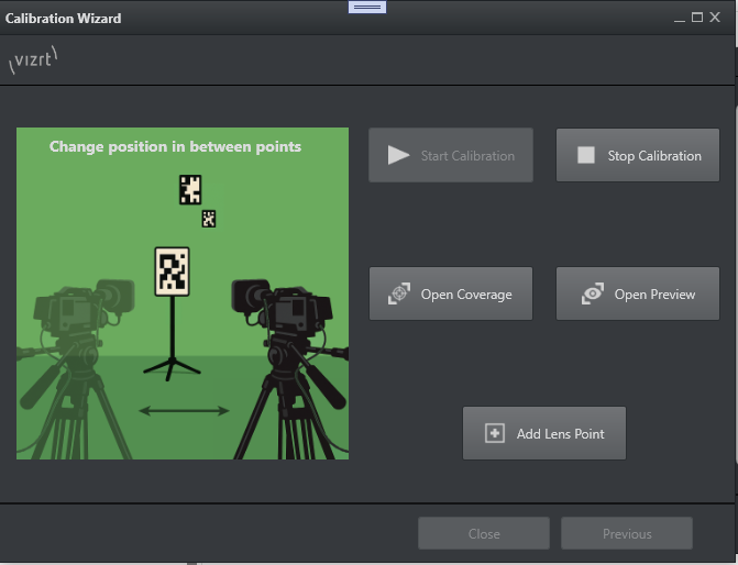
The Open Coverage button launchs an NDI window showing the calibration tool interface.
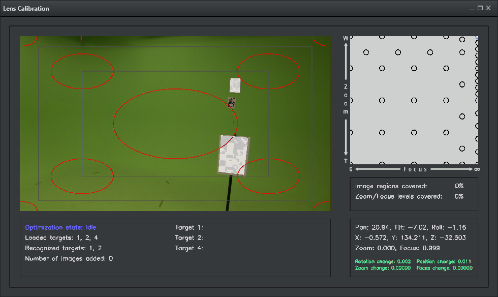
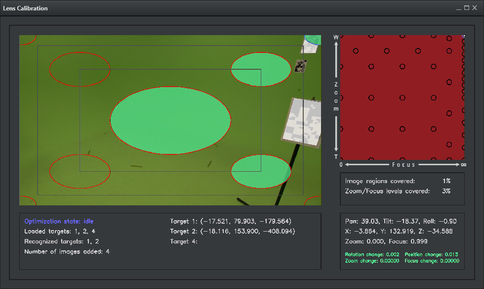
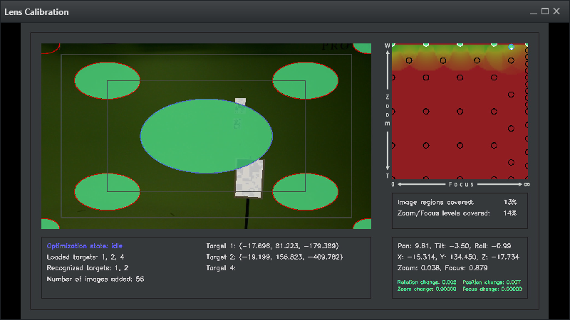
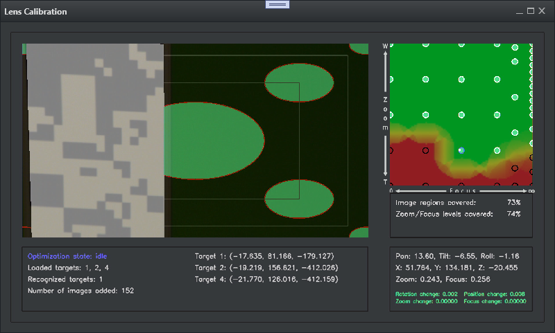
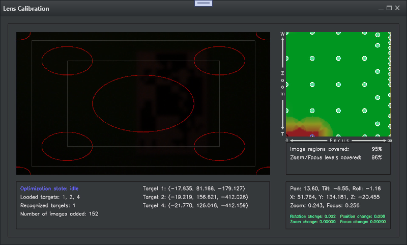
The coverage panel used for the actual calibration is divided into five sections.
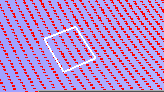
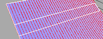
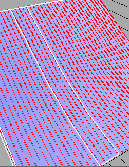
The video panel shows the camera frame, the detected targets rendered as white rectangles on top of the real targets, and nine elliptical shapes which represent the calibration hotzones for the targets to be detected. Once the camera is stable and a target is detected within a hotzone, the hotzone turns green, indicating that the process extracted a useful image covering this image area, with a target at the current zoom/focus level. The hotzones only become visible if the current camera zoom and focus are within one of several predefined areas as described below.
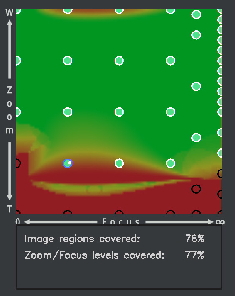
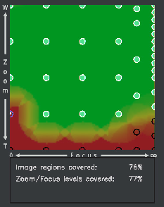
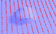
The graph on the right displays a heatmap of the calibrated lens related to zoom and focus. Red indicates an insufficient calibration, while green represents a fully calibrated area. The small circles are predefined zoom/focus areas, lens points, where the calibration can be done. While a rather dense distribution of zoom/focus points are defined by default, manual points can be added during the calibration if necessary (see Adding Points).
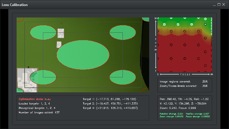
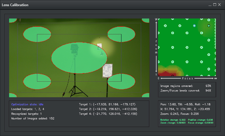
For each of the zoom/focus areas in the heatmap, the user should cover all of the hotzones displayed in the video panel.
The three other panels provide information about:
Covered calibration status in %.
Detected targets.
Incoming tracking data.
Lens Calibration Procedure
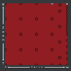
Start with the first point at zoom 0% and focus infinite (top right). If the white indicator for Focus is on the right side, flip the Focus direction (invert) in the Camera Rig in Studio Manager.
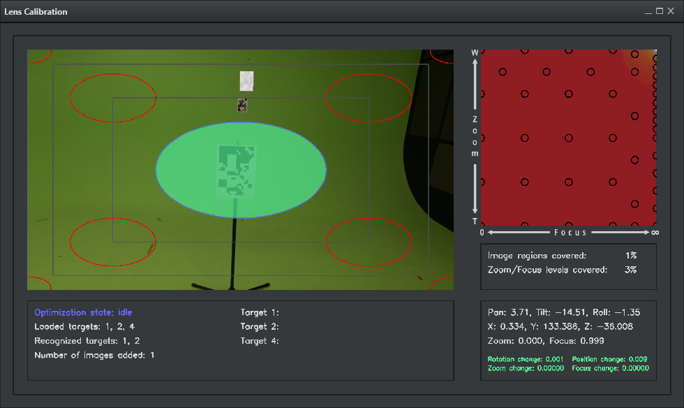
Start filling in circles/hotzones by panning/tilting the camera, so that the detected targets are within these areas. Try to vary the targets a bit between the different hotzones. As soon as a target is inside the hotzone, hold the camera still until the area is green.
Repeat these steps until all 9 hotzones are green, if possible. There might be unreachable areas, depending on Zoom and Focus level. In this case, leave the hotzone empty, a small amount of missing areas per lens should not affect the whole calibration result.
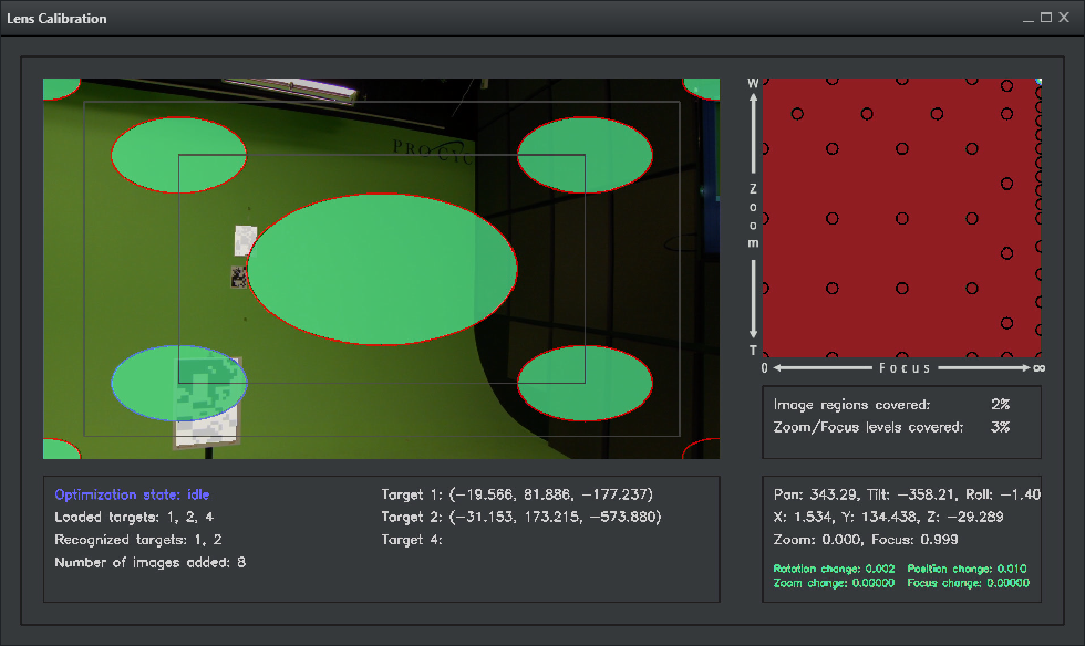
Once all of the hotzones are covered, the current zoom/focus area is covered. If for some reason it is not possible to cover some of the hotzones, the process still works. However, for optimal results, the process should cover all of the hotzones for as many zoom/focus areas as possible.
For optimal results, change the camera position at least when moving from one zoom/focus area to the next one.
Note: When calibrating a PTZ camera or a camera without tracking data for position, the camera cannot be moved during the calibration process. Position offsets need to be set up in the camera rig before starting the calibration.
Repeat the steps to cover the hotzones for each zoom/focus area (or as many as possible).
The UI starts drawing green areas indicating a good coverage of this lens area.
Note: This starts after a few points are made first.
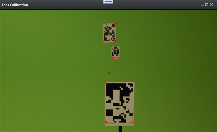
Blurry Targets
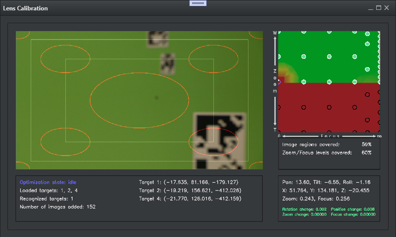
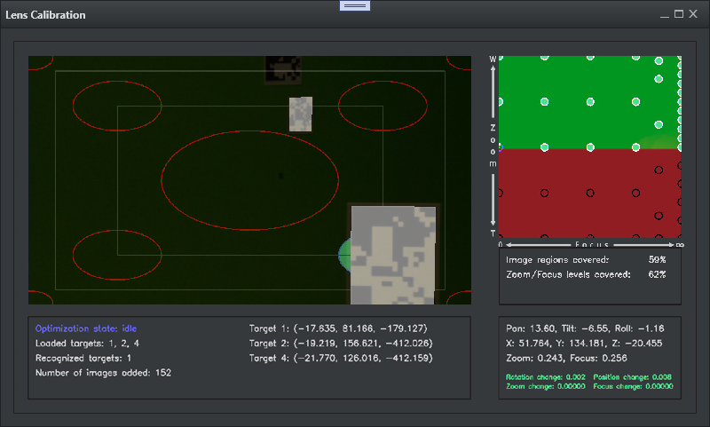
Change the iris and try to use lights on the targets to deal with blurry out of focus images (target detection stops working once the images are very blurry).
Try to use all targets as long as possible, and try to cover as many zoom/focus areas as possible.
The calibration heatmap serves as a quality hint, and can be a bit off during calibration and optimization. Additional zoom/focus calibration areas may be added to improve the quality, see Adding Points.
The more points added, the longer calculation needs. The optimization state in the bottom left coverage panel indicates whether the lens calibration process is currently busy updating the lens calibration, or whether it is idle. If it is idle, this means that all of the images captured are processed, and the lens preview should be up to date.
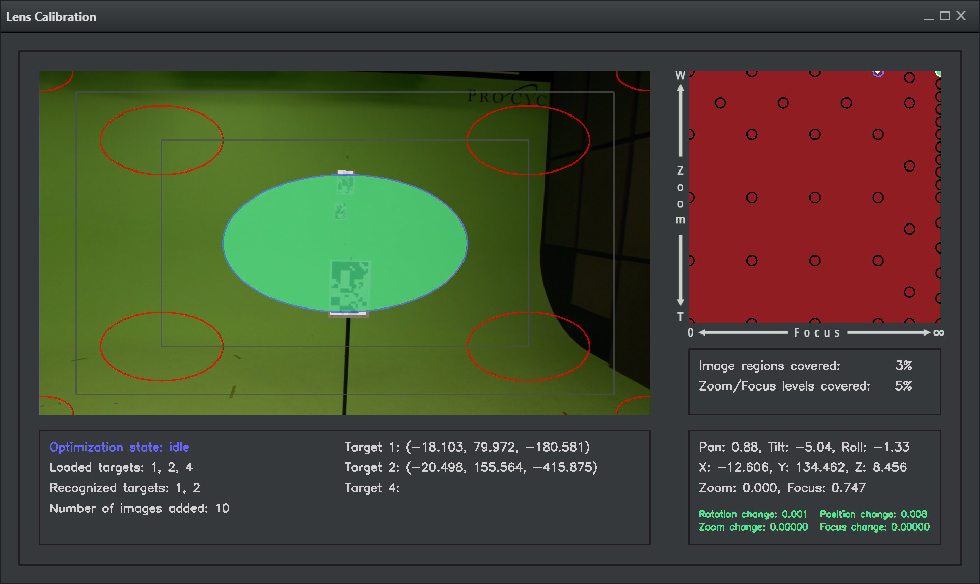
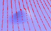
The example below shows how light can help to still be able to detect target in out of focus images (blurry areas).
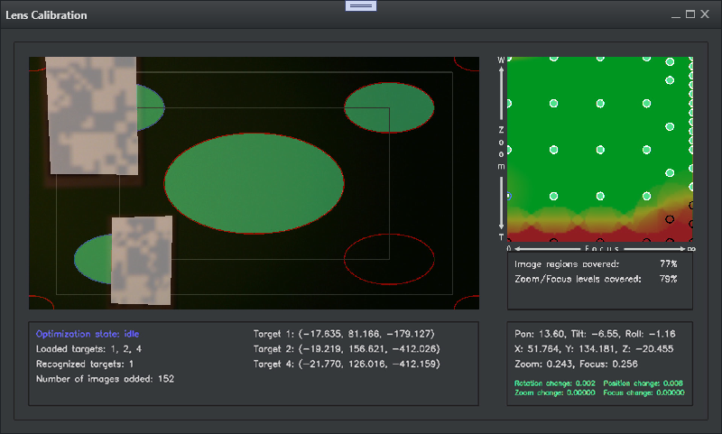
When the camera is zoomed in and the focus is close to zero (the bottom left of the zoom/focus coverage), it may become impossible for the calibration process to still reliably detect targets. This is expected, but the user should try to cover as many of those zoom/focus areas as possible.
Adding Points
Once all of the zoom/focus areas are covered, the user may interact with the camera and check the quality of the lens parameters by moving the camera, changing the rotation, the zoom and the focus of the camera.
The quality of the lens can be verified in the lens preview window, and the test scene. If there are zoom/focus areas where the quality is not as desired, the user can add additional zoom/focus areas to the calibration process to improve the results. Ideally, the user should add a zoom/focus area where the quality of the current lens calibration is the worst.
Lens Preview Window
The lens preview shows the current result of the calibration process. It uses the most recent optimized lens and target parameters, and is updated with the incoming video frames in real-time. This visualization can also be used to check the final quality of the calibrated lens. If there are areas of insufficient quality, you may add additional zoom/focus calibration areas (see Adding Points).
Note: To inspect the final quality, you must wait until all optimization processes have finished (Optimization state: idle).
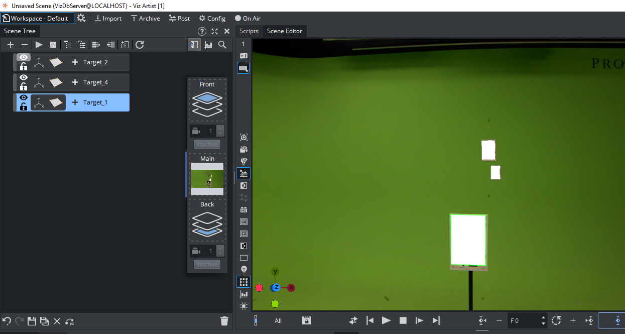
Test Scene
If the calibration was started through the wizard, a test scene is created automatically on start showing the rendered rectangles with the current calibration result.
The accuracy of the corners visualized in the lens preview window, should be the same as the accuracy of the rectangles rendered in the test scene. If the accuracy is not the same, it means there is an inconsistency between the results computed by the lens calibration process and the Viz Engine.
Note: The RectXYZ plugin is distributed with Viz Engine 5.4.0. For previous Viz Engine versions, the plugin must be copied manually to the Engines plugin folder C:\Program Files\Vizrt\VizEngine\plugin.
The plug-in can be found on the FTP under /products/VizVirtualStudio/.
Stop Calibration
Once all possible points are recorded, finish the calibration by pressing Stop Calibration. The Wizard closes and the lens file is automatically loaded to the current lens rig.
The file is displayed in the Lens File Editor.
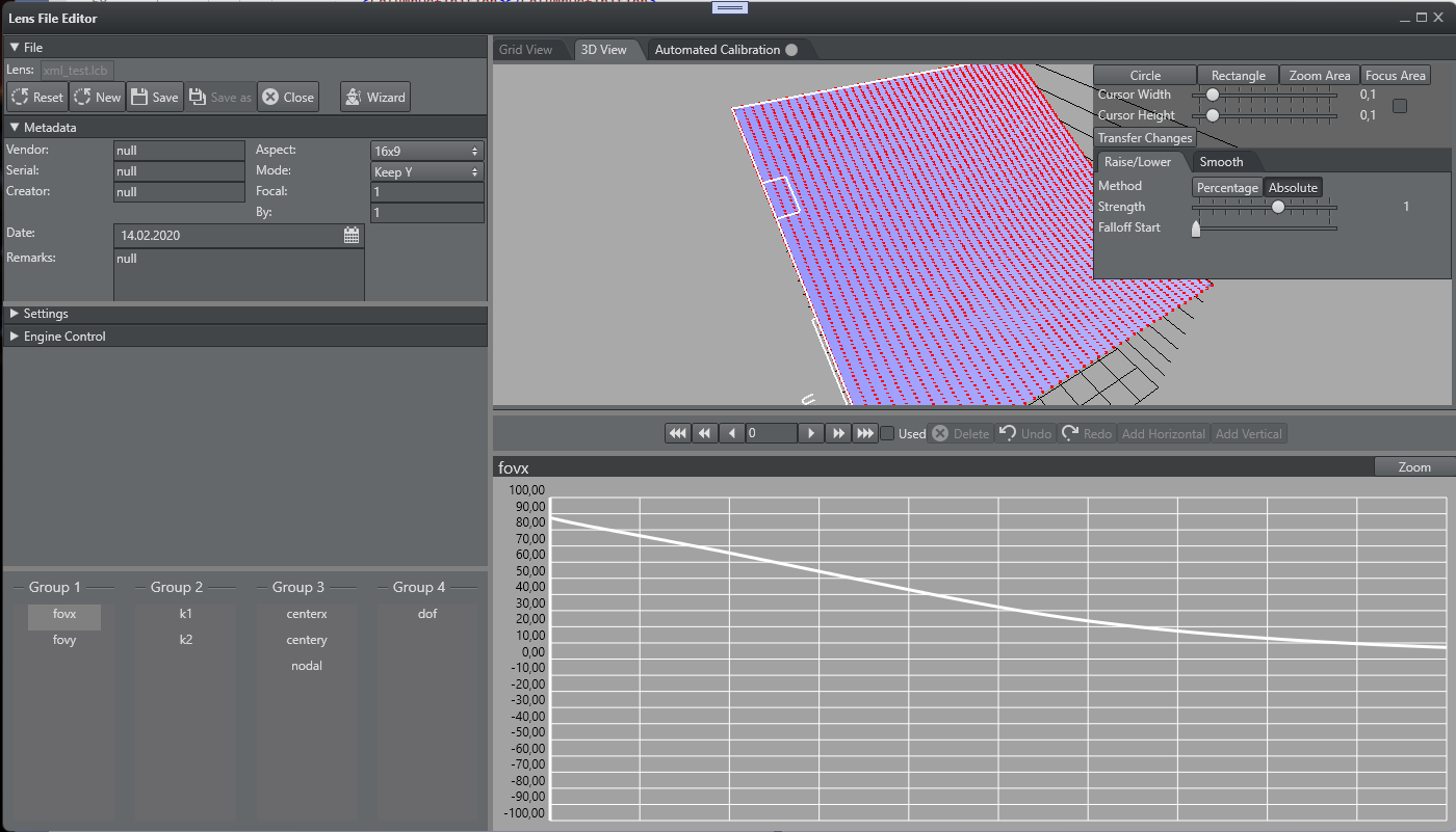
Editing Lens Points
It is possible to adjust the calibration result by lifting, lowering or softening areas of calculated points. As soon as a generated parameter map is selected, the tool window appears in the top right area of the 3D view.
Tool Window
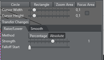
Cursor Selection
In the top area of the tool window the cursor type can be selected. It offers four types of cursors.
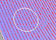
Circle
A circular or oval cursor. The size is defined by the Cursor Width and Cursor Height sliders. The size of the cursor can also modified by pressing CTRL and moving the mouse wheel.
Rectangle
A rectangular or quadratic cursor. The size is defined by the Cursor Width and Cursor Height sliders. The size of the cursor can also modified by pressing CTRL and moving the mouse wheel.
Focus Area
A cursor, which covers the complete focus area. Only Cursor Height is taken into account.
Zoom Area
A cursor, which covers the complete zoom area. Only Cursor Width is taken into account.
Operations on Points
Raise/Lower
Raises or lowers points in the cursor area. The strength falls off in direction of the cursor border.
Strength: Defines how many of the points are raised or lowered. Points are lowered when negative.
Falloff Start: Defines how far away from the border the falloff starts.
Falloff Start=0
Falloff Start= 1
Method: Changes the values:
Percentage: Changes by a percentage of its current value.
Absolute: Changes by a constant value.
Smooth
This averages all values by the sum of its surrounding points. This can be useful when peaks should be erased.
Save Lens
In order to permanently use the lens file, click Save.
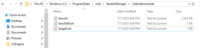
The raw lens files and other calibration results are temporarily stored in C:\ProgramData\vizrt\StudioManager\Calibrationresults.
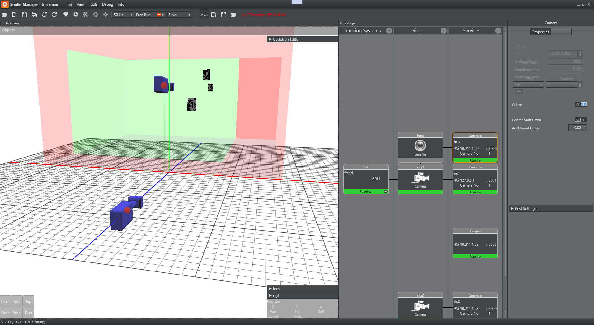
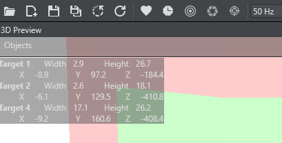
The Studio Manager displays the used targets in the 3D preview panel:
The HUD can be activated to show the detected Targets center coordinates.
Save the Studio Setup to finalize the calibration. Restart Tracking Hub to verify the lens file is loaded properly on restart.
Lens files are automatically saved in the lens files folder (C:\ProgramData\vizrt\VizTH\Lensfiles\).
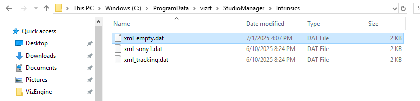
Target Detection Metadata
During the automated lens file calibration process, a intrinsics file for each lens is stored in C:\ProgramData\vizrt\StudioManager\Intrinsics.
This file is required if the lens is used for target detection later on. Please note that the intrinsics file requires the same file name as the lens file. This needs to be considered in case lens files get copied or altered manually.