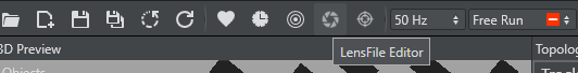
The Lens File Editor is now part of the Studio Manager. Open by clicking the Lens icon in the toolbar:
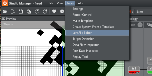
Or selecting LensFile Editor in the tools menu:
New Lens File Format
As the HTML based LensFileEditor uses groups for related parameters, the format of the lens file had to be changed. The new format is human readable XML.
Conversion from the old file format, which was used by Viz Engine and older Tracking Hub versions, is done by Tracking Hub during load time. All old lens files found in C:\ProgramData\vizrt\VizTH\Lensfiles are automatically converted to the new file format. The original files are moved to a folder named C:\ProgramData\vizrt\VizTH_ori\Lensfiles\old_lcb.
In Tracking Hub, it is then possible to add a lens file rig, which interprets the new file and sends the data to Viz Engine.
Lens File Editor
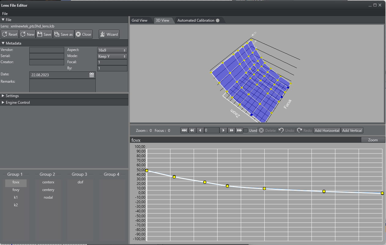
The main window consists of six regions or portals, and several modal windows.
Camera Selection
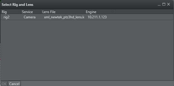
After the connection to Tracking Hub is established, the Lens File Editor shows all of the lens files ready to be calibrated. The Rig, Service and Engine (ID of the camera service) columns, identify the Rig/Camera combination to be calibrated. The Lens File indicates the name of the file loaded in the rig structure.
A lens file can be attached to more than one service. As the user selects a Rig/Camera combination, a copy of the lens file is loaded into the selected service. All other camera services are not affected.
When a combination is selected, it is locked in Tracking Hub, and can not be calibrated from another browser instance. The lock is released as soon as the browser window closes, therefore, it is possible to calibrate different lenses at the same time, but not the same rig/camera combination.
To start a calibration, select one of the table rows and press Calibrate. The window disappears and the lens data is loaded into the window.
Lens Area
File
The Save button forces Tracking Hub to store the lens data into the lensfiles/lensfile folder of the configuration directory. When selecting a combination of Rig/Camera, the name of the lens file is added into the File text field. When pressing Save, the loaded lens file is overwritten. Save As opens a popup where you can enter a new lens file name:
After pressing OK, the actual lens are saved on Tracking Hub, and automatically loaded. You need to save the configuration in Studio Manager to make the changed lens file permanent in the configuration.
New: Closes the lens file, and allows the user to start with a complete new calibration task. To generate the approximate field of view values, you need to enter the focal length and multiplication values into the info section, and press Default Values to calculate an approximation.
Close Lens: Releases the file lock from these lens, and closes the calibration process. The user is presented with a dialog to select a new rig.
Note: You need to press the Reload button in Studio Manager to select a new created lens file.
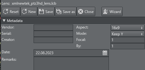
Metadata
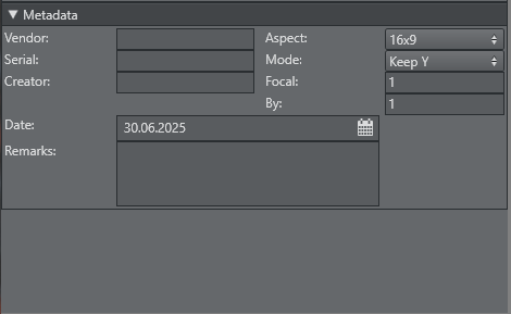
All fields should be filled with care, especially the Focal Length and Focal Multiplier fields. In case of new lens, the Lens File Editor calculates base FoV values out of this information. The dialog only accepts float numbers in the Focal Length and Focal Multiplier fields. The Aspect mode defines if the lens are used as 16x9 of 4x3.
Info: Tracking Hub calculates the field of view X value from field of view Y. During calibration, this value defines how Tracking Hub adjusts these values while dragging a point. Afterwards, this value is defined in the lens file rig of Tracking Hub.
Settings
In the settings section, you can adjust the catch range of the Autocatch feature (see Point Matrix), and the new Line Limit.
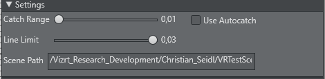
The line limit is used to prevent creating too many lines near one another, although in some cases, it is required to create more lines closer to each other. This can happen when calibrating big zoom lenses for sports.
The default value is 0.03, meaning that a new line must be 3% distant to another line.
The Scene Path is the path to a calibration scene in Viz Engine. This calibration scene is not installed with Tracking Hub, and has to be added manually if needed. Its location path can be set in the UI field, but the best approach is to enter the UUID of the scene there.
This is the scene loaded when using the Load Scene button in the Engine Control section Calibration Scene.
Group Portlet
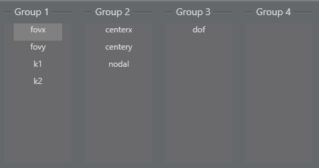
The Lens File Editor introduces the new concept of parameter groups. The old Lens File Editor only had the principle of measure points.
While field of view (FOV) and deformation parameters k1 and k2, have to be adjusted for minor zoom and focus changes, center shift and nodal point values, do not show this sensitive behavior. For these parameters, only a few calibration points are needed, whereas for FOV at least 25 (5x5) or more measure points are necessary. These points are defined by the crossing of horizontal and vertical zoom, and focus lines that can be moved, deleted and inserted at any time during calibration.
By moving a parameter from a 7x7 group into a 2x2 group, only four parameters are mapped into the new group.
Tip: Always create the groups before you start calibration.
Engine Control
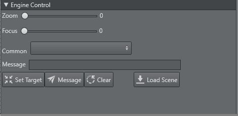
The Viz Engine portlet works in combination with the calibration scene.
It is also possible to select one of the common messages in the Common drop box, or enter any other message in the Message text field. By clicking the Send Message button, the message is displayed on the Viz Engine screen, and can be cleared by clicking the Clear button.
The Load Scene button forces Viz Engine to load the scene the user entered in the Calibration Scene of the settings section.
Important: The calibration scene is only for the Viz Engine Classic Render Pipeline. Please make sure your scene uses the Classic Render Pipeline scene in the Main layer.
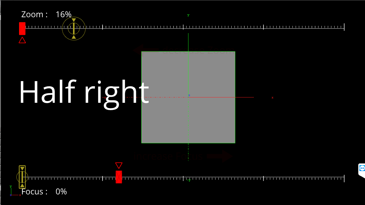
Calibration Scene
Viz Tracking Hub comes with a default calibration scene (as viz Archive). This scene is designed to be used with the lens file editor, and allows interaction with the camera operator.
Info: The archive of this scene is located on the FTP Tracking Hub download folder.
Info: The scene is loaded by default into the Front Layer of Viz Engine.
The scene must be imported into the database, and then loaded into the Front Layer of Viz Engine. In combination with the Engine Control portlet, the person running the calibration of the lens, can communicated with the camera operator.
This special scene shows the target points that need to be calibrated by changing zoom and focus values, and visually assist the operator. New target points can be sent to Viz Engine using the Send button. Whenever a new point is selected, whether in the 2D or 3D portlet, the new zoom and focus values are set in the Zoom and Focus fields of the Engine portlet.
Parameter Control and Views

The Parameter portlet and the 2D and 3D views work closely together. Whenever a point or line is selected in the views, the parameter control changes to the selected value, and reflects all possible input on the selected objects.
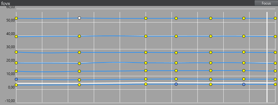
With the 2D View Controls, a user can select the diagram type of the 2D display. Type can define two values, Zoom and Focus:
Focus: The X axis defines the focus range (
0to1), while the Y axis shows the value of the calibrated points.Zoom: The X axis defines the zoom range (
0to1), while the Y axis shows the value of the calibrated points.
During calibration, the focus diagram is the preferred one.
In case of a selected point, the value of the point can be modified. The modify divisor defines the amount of change, when the user clicks on the up and down buttons of the value. The base of this value is defined as the zoom area in the 2D and 3D view. 10 means that the value is increased or decreased, the zoom is divided by 10, 100 or 1000. This is valid for line movement as well.
A selected line can be moved between its left and right, or upper and lower neighbor. The Modify Divisor again defines the step size of the movement.
As soon as a point has been modified, the point is displayed in yellow and its value are used in the spline interpolation. The yellow state can be cancelled by unchecking the Used checkbox, and it activates the blue state of the point, defining its value from the calibrated points around.
3D View
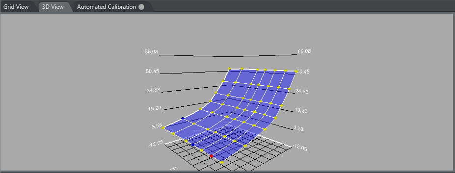
The 3D View shows the lens in a 3D Diagram. Focus is drawn in the X-Axis, and Zoom in the Z-Axis. The lens are drawn as a blue surface, and the measure points as spheres. Depending on the status of the measure points, different colors are used.
By clicking on the Points button, the display can be changed to a 2D view of the measure points.
Navigation in the 3D View
Rotate the view by right clicking into the view, hold the right mouse button and drag the mouse. Move the view by clicking into the view, hold the right mouse button and press SHIFT.
Zoom: Zoom in and out with the mouse wheel.
Point Selection
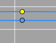
A point can have three statuses:
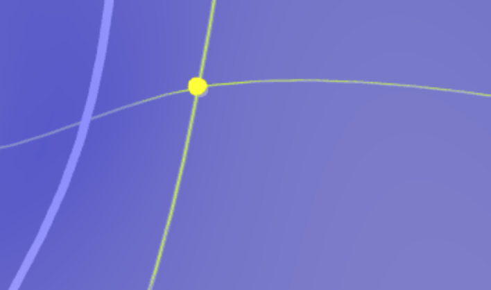 A mandatory point is drawn as a yellow sphere. | 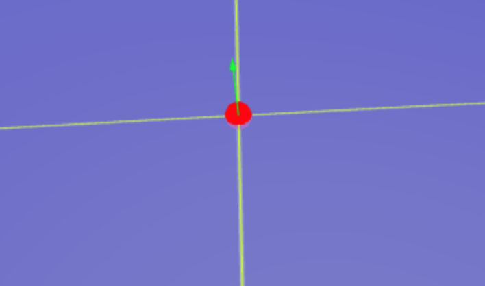 When the point is selected, its color changes to red. | 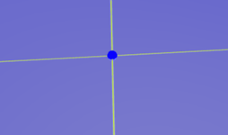 A point that is not mandatory and is untouched, is drawn in blue (such points are only calibrated if needed). If untouched, the point is placed on the surface of the spline. A selected, untouched point is drawn as light blue. As soon as the point is moved by the operator, it changes to touched. |
Point Selection
Clicking the point selects the point and changes the parameter control.
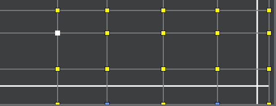
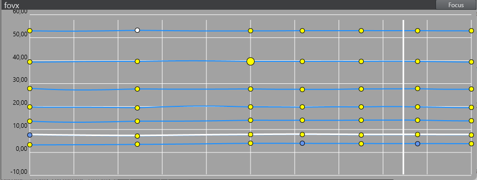
Point Matrix
The point matrix displays all points and lines of a group. The X-axis represents the focus, and the Y-axis the zoom value of a point. Zoom and Focus are normalized to the width and height of the Portlet. Points can be selected by clicking on the rectangle, and lines can be selected by clicking on them.
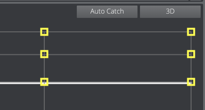
If Auto Catch is activated, the point under the cross hair is selected when the distance of zoom and focus of the point goes under a limit. If the cursor is out of range it is red, and as soon as it comes into the range of a point, it becomes white.
Used points are displayed as yellow rectangles, while unused points are in blue. If a point is selected, it is white.
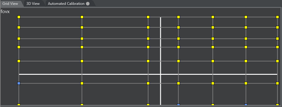
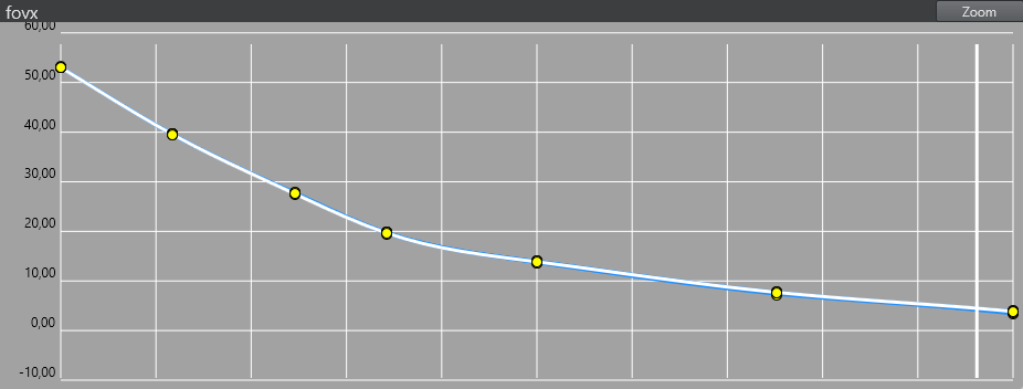
2D View
The 2D View is the main view used for calibrating the lens points. Clicking into a point, selects the point in 2D View and 3D View, and dragging the point manipulates the value. Using the mouse wheel, you can zoom in and out (and increase the accuracy of the manipulation).
Navigation in the 2D View
Move: Left click with the mouse in the 2D View, keep the left mouse button pressed and move the mouse. This moves the diagram.
Zoom: Use the mouse wheel to zoom in and out.
Different States of Points | |
|---|---|
 A point that is not mandatory and untouched (blue), and a touched point (yellow). | 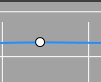 A selected point. |
The 2D view can be switched between Zoom and Focus mode (upper right).
Shortcut System
The lens file editor implements a shortcut system, enabling the user to operate the editor with keyboard shortcuts only.
Shortcut | Change Parameter |
|---|---|
CTRL + 1 | Field of View X |
CTRL + 2 | Field of View Y |
CTRL + 3 | K1 |
CTRL + 4 | K2 |
CTRL + 5 | Center X |
CTRL + 6 | Center Y |
CTRL + 7 | Nodal |
CTRL + 8 | Depth of field |
SHIFT + Down | Increases the value of the selected point for 1/1000th of its actual value |
SHIFT + Up | Decreases the value of the selected point for 1/1000th of its actual value |
CTRL + Down | Increases the value of the selected point for 1/100th of its actual value |
CTRL + Up | Decreases the value of the selected point for 1/100th of its actual value |
SHIFT + CTRL + Up | Increases the value of the selected point for 1/10th of its actual value |
SHIFT + CTRL + Down | Decreases the value of the selected point for 1/10th of its actual value |
ALT + Cursor Keys | Moves selected point for one row or column |
CTRL + R | Rescales 2D view |