The Target Detection feature can be used to receive the coordinates of a physically placed target inside the studio. This can help start an existing working setup.
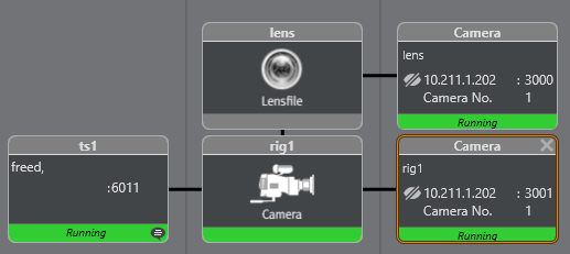
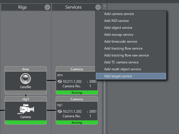
Create a service for the engine, and a service for target detection.
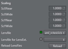
Assign the appropriate lens file for the used camera, and lens (the one created in the automated lens calibration process).
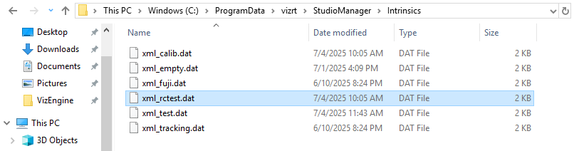
During the lens calibration process, a lens file is created along with an intrinsics file (.dat). The lens file and the intrinsics file have the same name, for instance xml_rctest.lcb and xml_rctest.dat.
Intrinsics files contain additional lens information that is required for subsequent target detection. The lens file loaded in the studio manager references the appropriate intrinsics file (for example, in the info field intrinsics_file="xml_rctest").
Note: These files can be found in the Studio Manager folder, and must not be renamed.
Lens files containing a related intrinsics file, appears in the file picker dialog.
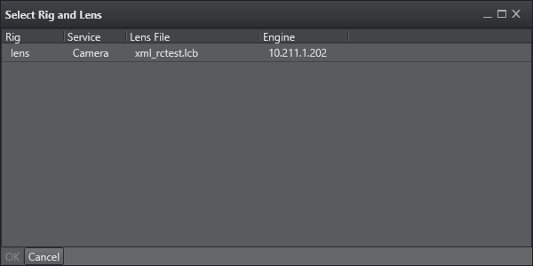
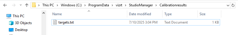
Loading a file, starts searching for target calibration results stored in a separate file (C:\ProgramData\vizrt\StudioManager\Calibrationresults). This file is created once the target calibration process is running. Like the lens file calibration, the target detection can be done by using the input of a Viz Engine scene, or any existing NDI stream.
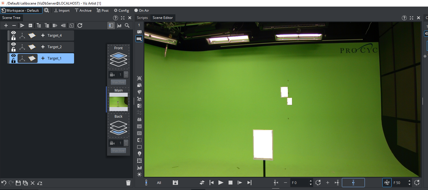
Viz Engine Scene Preparation
If the input on a local Viz Engine is used, a simple scene needs to be created. Therefore, the input needs to be added to the scenes Media texture assets.
Add it to the media panel or,
Drag the media asset to the scene settings background image (the texture asset is created automatically).
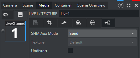
The media asset SHM Aux Mode, needs to be set to Send, to share the input with the local calibration tool.
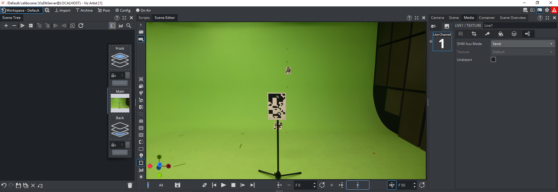
Set Engine to On Air.
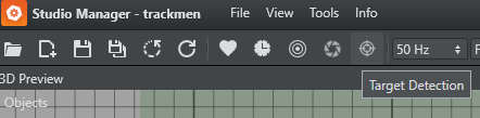
Target Detection Wizard
Similar to the Calibration Wizard, the target detection needs to be configured by choosing the used input, and the targets set up in the studio.
 Launch detection. | 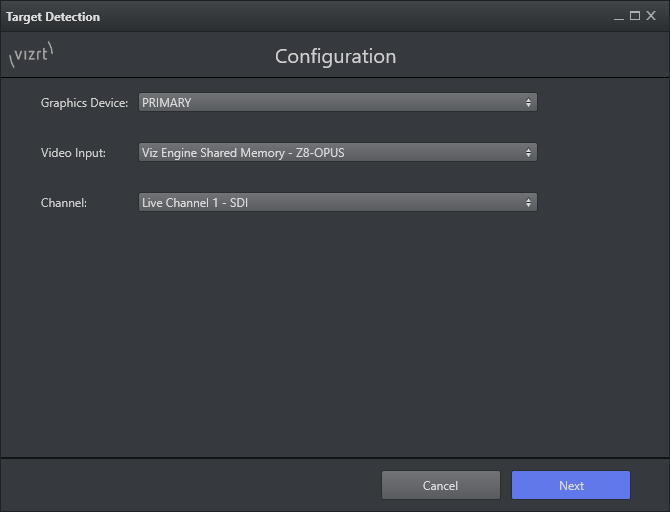 Setup the use case configuration. | 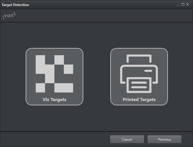 Choose the target mode. |
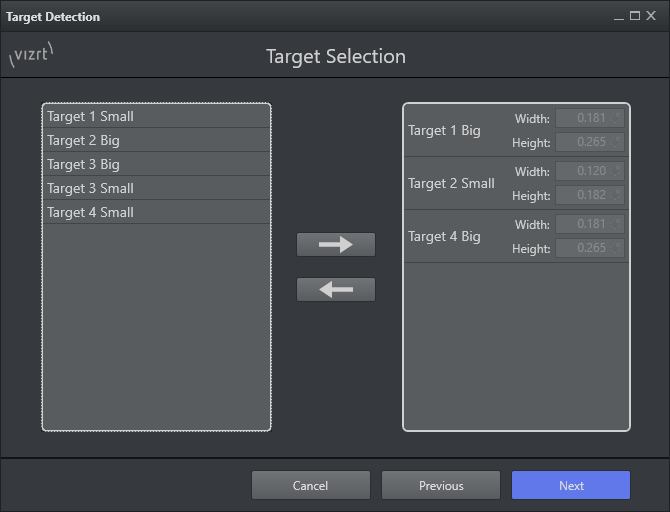 Choose the targets used in setup. | 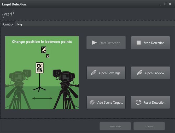 Start detection and open coverage view. |
Automated Target Localization
The target localization process uses the pre-calibrated lens parameters from the intrinsics file, to automatically determine target positions in the coordinate system of the camera tracking system. Compared to the full lens calibration, the target localization requires far less images.
For optimal results, the chosen targets should be captured in different image regions, and across several zoom levels. The focus can be set to infinity, or to a level that provides sharp images.
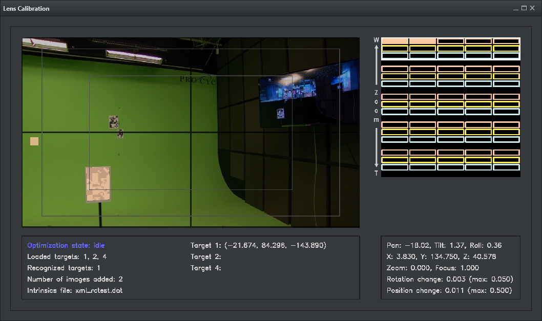
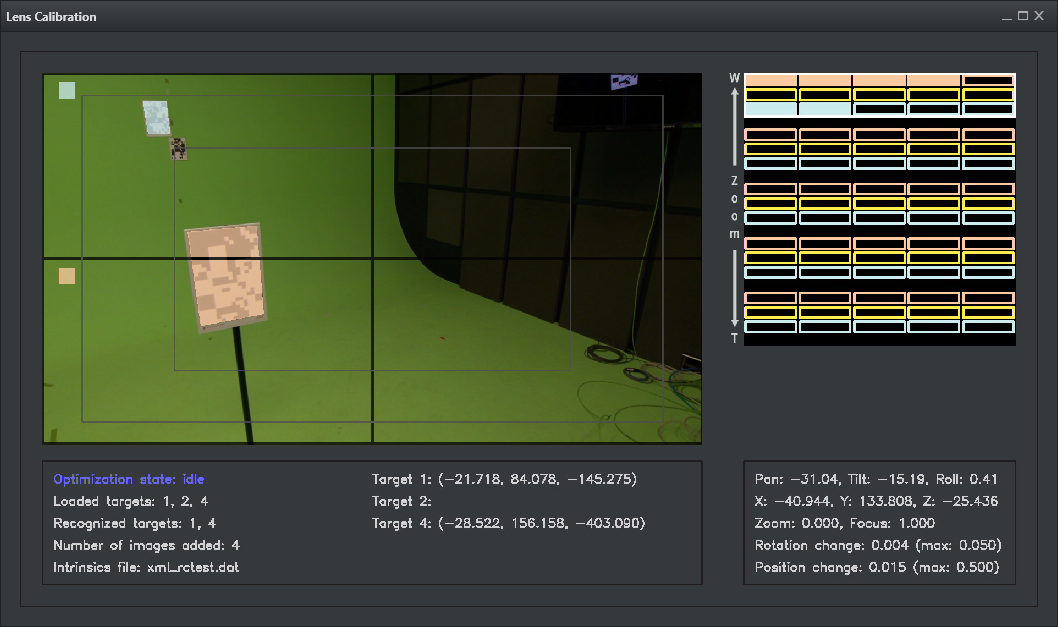
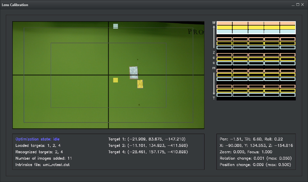
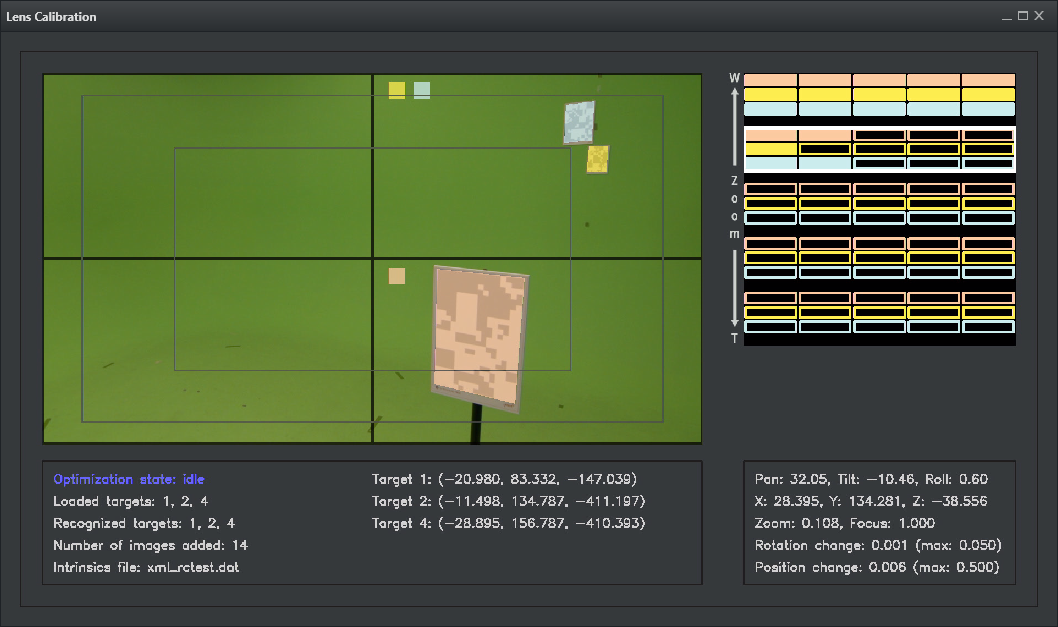
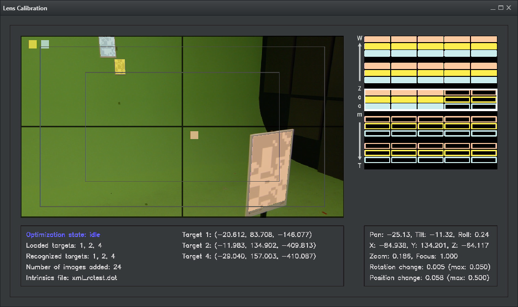
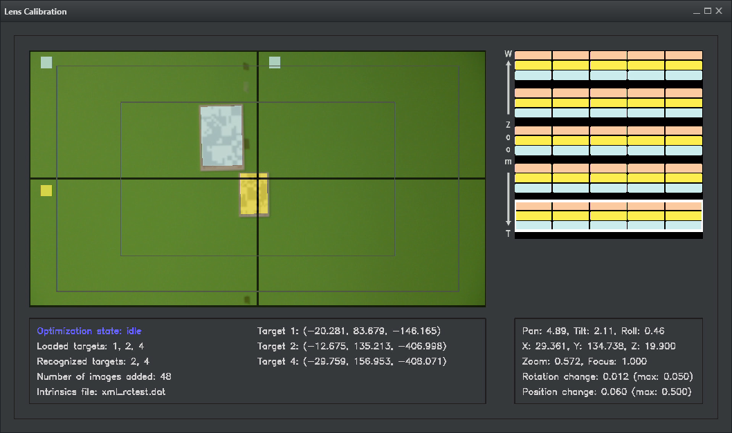
Target Coverage
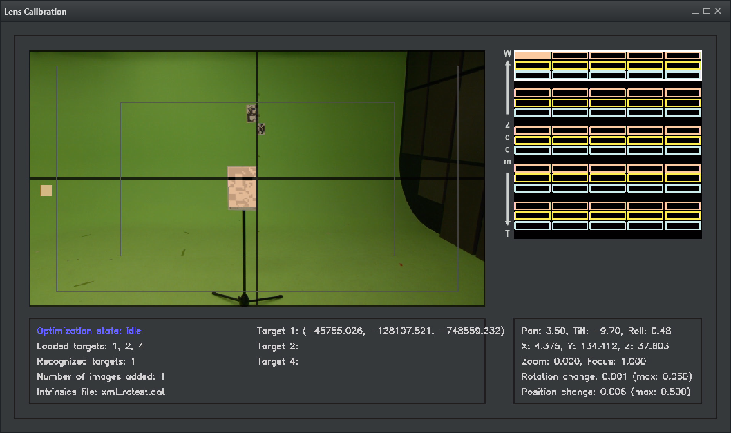
The input image is split into 4 regions. The top left corner of each image indicates which target was captured in this region. Every target can be captured once in every image region.
The graph on the right shows how well the zoom levels and the different camera positions are covered. The zoom is split into 5 levels (vertical axis), and every zoom level is split into 5 camera positions (horizontal axis). Targets are color coded, and there is one row for each target for each zoom level.
The panel at the bottom left shows the current positions computed for the targets.
For accurate results, it is usually not necessary to cover the full zoom and position range. You may capture the targets in different image regions on several zoom levels, from different camera positions, and validate the result using the target preview, or, the Viz Engine Scene by moving the camera around and changing its zoom. If it is accurate enough, the process can be stopped. Otherwise, you should try to capture more images.
Before stopping the process, wait for the optimization state to become idle.
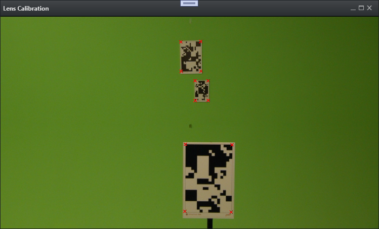
Target Preview
Similar to the lens calibration, the current results can be observed in the target preview. The preview and the Viz Engine Scene can be used to check the accuracy of the target positions, and to determine when to stop the localization process.
Target Localization Procedure
Start with the first camera position. Pan and tilt, to detect targets in all 4 areas.
Try to successfully capture all targets in the different image regions. Repeat this step for different camera positions.
Up to 5 camera positions can be stored for a chosen zoom level. It is not mandatory to fill out all 5 positions, but by choosing more positions, the results improve.
Repeat the steps above for other zoom levels.
The detected target position is automatically streamed stored.
In general, the more zoom levels and camera positions per target, and the more image regions for each of those combinations are covered, the more accurate the results. However, in practice, it is usually not necessary to cover everything. You can use the preview, and the Viz Engine Scene to check its quality. If it is accurate for all the positions and zoom level, you may operate. The process can be stopped earlier, but wait for the optimization state to become idle.
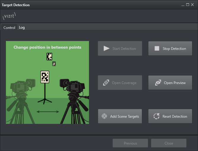
The Wizard offers the option to reset the detection, and start from scratch.
The Add Scene Targets button creates containers in the existing, currently loaded Viz Engine scene.
RectXYZ is copied to a separate container, and filled with the detected coordinates for each target. This allows to show the targets in any existing VS/AR scene, without creating them manually.
The targets coordinates are also stored in a separate file at C:\ProgramData\vizrt\StudioManager\Calibrationresults. The file gets reset every time a new detection starts.
Target Service
In order to stream the targets result into the engines shared memory, a target service can be used. This allows the usage of the detected coordinates within a scene (for example, by using scripting to implement an alignment logic of containers/objects according to a targets position).
Set up the port the engine is using for shared memory configuration (setting can be found in Communication → Share Memory Tab). By default, no port is set in the engines config (see image below).
Note: The Engine needs a restart when the port is set or changed.
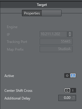
A Map Prefix can be added to each shared memory map to avoid conflicts with other studios/scenes.
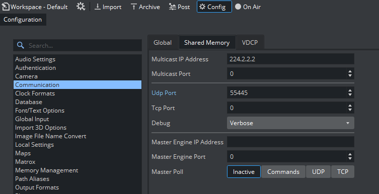
The Debug section prints incoming packages when set to Verbose.
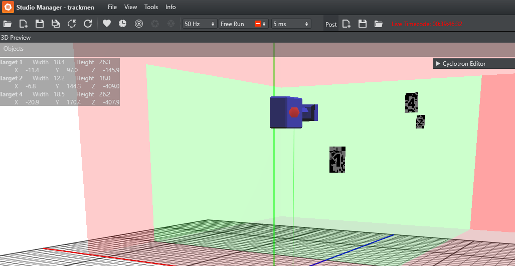
Studio Manager Preview
Withing the Studio Manager, a Target HUD can be activated in the View settings. This shows the currently detected center of each physical target. The 3D preview renders the targets as well.