Vision Mixer Settings
There are several settings required for Viz Mosart to effectively control a specific video mixer.
Vision Mixer Configuration
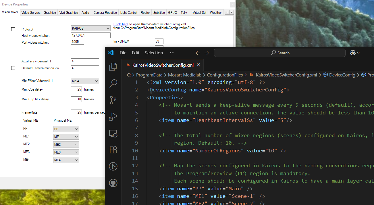
When configuring a vision mixer, the Vision Mixer tab in the Device Properties window links to any additional configuration file used by the driver.
To modify a vision mixer configuration file
Open AV Automation, navigate to Device Properties > Vision Mixer tab > [Select Protocol].
When a device is selected, either
There is a corresponding configurations file that contains additional settings:
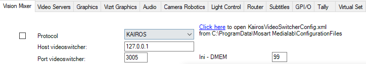
This is indicated by the text Click here to open xxx.
In the example below, a Ross settings file is already located at C:\ProgramData\Mosart Medialab\ConfigurationFiles.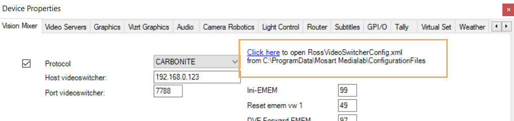
Follow Click here to edit the configurations file.
There is no corresponding configurations file:
You can copy an unused default file from the Installation folder.
This is indicated by the text Click here to copy xxx.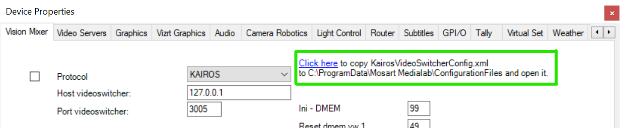
Follow Click here.
The information text changes to Click here to open xxx, as the file now exists for editing, in a standard configuration file folder.
Follow Click here to edit the configurations file.
The configuration file opens in your default XML file editor.
Usage Notes
Information about any configuration file will not appear if the device does not require a configuration file.
Configuration files are used to configure additional settings.
See section Vision Mixer Configuration Files for examples.The standard configuration file folders are
C:\ProgramData\Mosart Medialab\ConfigurationFiles
C:\channeltemplates
If the configuration file is found in both
“C:\ProgramData\Mosart Medialab\ConfigurationFiles” and
“C:\channeltemplates”,
the path “C:\ProgramData\Mosart Medialab\ConfigurationFiles” is prioritized.
The Video Mixer Menu
Info:
Most devices, especially ones controlled through IP, often have their own configuration interface (for example, accessible through a web page) where various parameters such as host/port can be inspected and modified as needed.
Use the values found in the device configuration interface when setting their corresponding properties that are described below.
Protocol (check box): Check the box to enable video switcher control.
Protocol: Select a protocol supported by your switcher:
ACUITY (See Info below)
CARBONITE
Info
For ACUITY and CARBONITE video switcher protocols, a new physical ME named ME0 is introduced.
ME0 shall be used to address the P/P on newer/updated Ross video switchers.
Set this up under AV Automation > Device Properties > Vision Mixer > [Protocol = CARBONITE|ACUITY].
This ME naming can, for example, control a Ross Carbonite Ultra video switcher from Viz Mosart.For Carbonite, the MiniME-related settings control the corresponding MiniMEs regions on the switcher, while for Ross Acuity these settings are used to control the B-side of the corresponding mixer region.
GVG200: GVG/Philips/Thomson
GVG4000: Ross Synergy
GVG4000 V2
GV CPL
GV DD35
GV KAYENNE PRIMARY
GV KAYENNE SECONDARY
GV ZODIAK
KAHUNA: Snell/Grass Valley Kahuna/Kula (a dialect of SONY)
KAHUNA IP: Grass Valley Kahuna/Kula (a dialect of SONY)
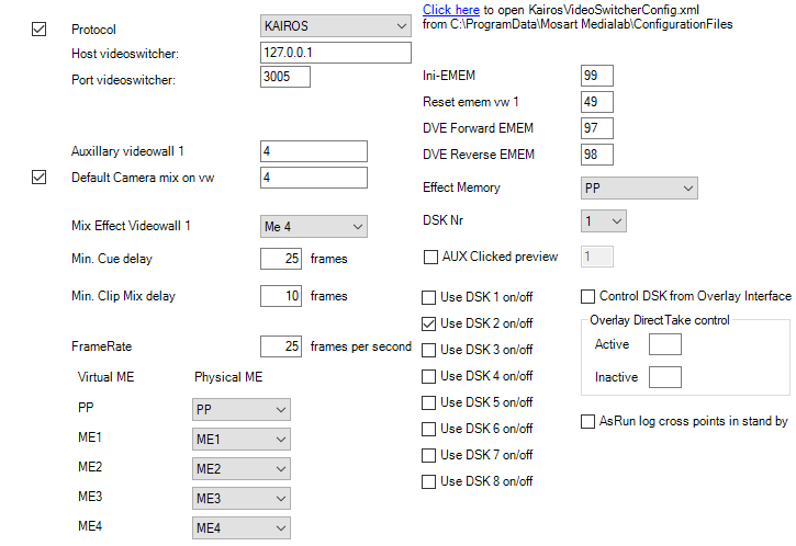
KAIROS
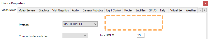
MASTERPIECE
NOVA700: Echolab
SONY: Sony compatible video switchers
SONY BVS: Support for legacy SONY DVS/BVS 300 series
SONY MVS: An extension to the protocol for the SONY MVS8000
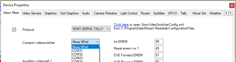
SONY SERIAL TALLY
SONY SERIAL TALLY IP
VIZRT ENGINE
See also Viz Engine as a Switcher.TRICASTER (was VIZRT-IPS)
See also: TriCaster and Viz Mosart.
Comport videoswitcher: Defines the serial port the video switcher is connected to.
Host videoswitcher/Port videoswitcher: Defines the IP host address and port of the video switcher.
Auxiliary videowall 1: This is the auxiliary output from the video switcher to the video wall.
Default Camera mix on vw (check box): Enables the default camera in program when entering video wall mode.
Default Camera mix on vw: Enter the camera number you want to use as the default camera in program when entering video wall mode.
Mix Effect Videowall 1: Select the ME to use when enabling mixing in video wall mode.
Min. Cue delay: Value in frames which sets the minimum delay before Viz Mosart cues the next template in preview.
Min. Clip Mix delay: Value in frames which sets the minimum delay from starting the server to starting the video switcher transition.
FrameRate: Specify the number of video frames per second for the system.
Ini-EMEM: Initial register to recall when starting the automation. Depending on the Protocol chosen, the caption may alternatively be Ini - DMEM or Ini - SNAPSHOT.
Reset EMEM vw 1: Register to recall to normalize the ME before entering video wall mode.
(Depending on the Protocol chosen, the caption may alternatively be Reset dmem vw 1 or Reset snapshot vw 1).DVE Forward EMEM: (not supported by Sony) EMEM to recall for running DVE forward. (Depending on the Protocol chosen, the caption may alternatively be DVE Forward DMEM or DVE Forward SNAPSHOT).
DVE Reverse EMEM: (not supported by Sony) EMEM to recall for running DVE backward. (Depending on the Protocol chosen, the caption may alternatively be DVE Reverse DMEM or DVE Reverse SNAPSHOT).
Effect Memory: ME to use when recalling registers for Effect use.
DSKNr: Downstream keyer to use for the DSK on/off functionality.
AUX Clicked preview (check box and number): Check the box to enable AUX clicked preview, and specify the AUX bus connected to the preview monitor. When activated, it is possible to click an element in the Viz Mosart rundown, to preview the source on the monitor, via the specified AUX bus.
Use DSK n on/off: Enable or disable the on/off functionality for DSK 1-N, where N depends on the protocol. Most protocols have 4 DSKs, but there could be as many as 8 DSKs.
Control DSK from Overlay Interface: Check box to enable DSK to be on only when overlay graphics is present.
Overlay Direct Take control:
Active: Viz Mosart will run the direct take entered here when an overlay graphic goes On Air.
Inactive: Viz Mosart will run the direct take entered here when an overlay graphic goes Off Air.
AsRun log cross points in stand by (check box): Check box to set AsRun log in stand-by.
Common Video Mixer Connection Settings
The following table presents some recommended or additional values for a range of video mixer drivers.
Driver | Settings | Configuration Interface Notes |
|---|---|---|
KAIROS | Port video switcher: 3005 | |
GV CPL | Port video switcher: 5000 Client Port video switcher: 6004 | This driver uses UDP protocol Additional client port property used for receiving callbacks |
Sony | SonyVideoSwitcherConfig.xml setting <item name="ReadTimeout" value="100" /> | ReadTimeout is possible to change in the SonyVideoSwitcherConfig.xml configuration file. |
Sony Serial Tally | SwitcherTypeVariant (in settings, with Ctrl+Shift+S ) should be set to SonyCom. | |
Sony Serial Tally IP | SwitcherTypeVariant (in settings, with Ctrl+Shift+S ) must be cleared. SonyVideoSwitcherConfig.xml setting <item name="ReadTimeout" value="100" /> | ReadTimeout is possible to change in the SonyVideoSwitcherConfig.xml configuration file |
VIZRT ENGINE | When working with a Viz Engine in a switcherless, or Engine Switcher configuration, refer to the specific settings in section Viz Engine as a Switcher. | |
TriCaster |
Moxa NPort device as the COM port
In Comport videoswitcher you can select Moxa NPort for devices using the following protocols:
SONY
SONY BVS
SONY MVS
SONY SERIAL TALLY
KAHUNA
To use a Moxa NPort device as the COM port
Configure the Moxa NPort device:
Open the administration panel of the device and for the given serial port (Port 1 in this example) navigate to the Operation Modes section:
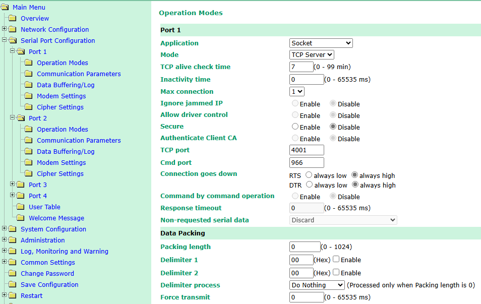
From the Application dropdown menu, select Socket.
From the Mode dropdown menu, select TCP Server.
Leave all other settings with their default values, but see Info below.
Note down:
The value of TCP port.
The value of Cmd port.
The device’s hostname/IP address.
Info: In the Operation Modes panel, if the value of Max Connection is more than one, then set Allow driver control to Enable.
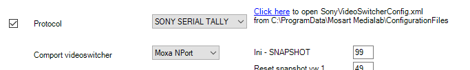
Configure AV Automation:
From the AV Automation menubar, select Devices > Properties > Device Properties > Vision Mixer tab.
On the Vision Mixer tab, from the Protocol dropdown menu, select one of the supported protocols.
From Comport videoswitcher, select Moxa NPort.
Open the configuration file SonyVideoSwitcherConfig.xml by following the Click here link (next to Protocol).
The configuration file opens in your default text editor.
Modify the following settings in SonyVideoSwitcherConfig.xml, using the values you noted down earlier:
MoxaNPort:
value="<hostname_or_ip>@<tcp_port>:<cmd_port>"hostname_or_ipis the hostname/IP address of the Moxa NPort device.tcp_portandcmd_portare the two ports configured above for Port 1, for example: 192.186.1.123@4001:966.
ComPort2:
value="Moxa NPort"This is used to set up the second serial port for the SCU connection, when needed by the switcher.
MoxaNPort2:
value="<hostname_or_ip>@<tcp_port>:<cmd_port>"
This is used to set up a second serial port for the SCU connection when needed by the switcher:hostname_or_ipis the hostname/IP address of the Moxa NPort devicetcp_portandcmd_portare the two ports configured above for Port 2, for example: 192.186.1.123@4002:967.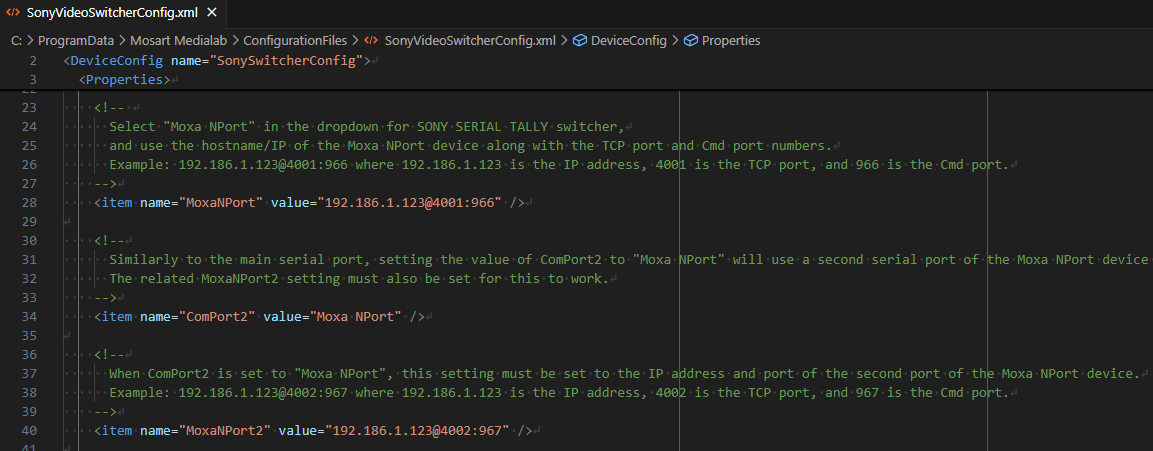
Restart AV Automation
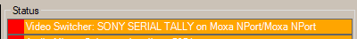
Working status
The Video Switcher status shall indicate that the Moxa NPort device is used for one (or both) serial ports: