Use the Video Output section to configure special settings for video output, such as SPG settings and so on.
Video Output Properties
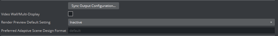
Sync Output Configuration: Opens the Video Output Editor. You can also open the Video Output Editor by pressing ALT + V.
Video Wall/Multi-Display: Sets the main output to the Digital Visual Interface (DVI).
Important: For video wall setups, this setting must be active and the output format must be set to FULLSCREEN.
Render Preview Default Setting: Sets the default value for the Preview button (see Control Buttons), when Viz Engine is in On Air mode.
Inactive: Renders only video out signals. This increases performance, as the renderer does not have to render into an editor on-screen and into pixel buffer.
Active: Renders both video out signals and on-screen (this decreases performance).
Fullscreen: Sets the On Air window to screen size.
Preferred Adaptive Scene Design Format: Defines which adaptive format to use. If, for example, a scene holds a portrait format, this format is used instead of the default format.
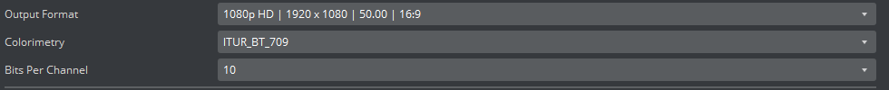
Output Format / Colorimetry / Bits Per Channel
You set the output format, colorimetry, and bits per channel of the rendering engine using these combo boxes. All video hardware configurations are associated with the video standard set here as the output format. This setting also defines the frequency (frame rate) at which Viz Engine runs.
For PAL and NTSC, you can set the aspect ratio to 4:3 (standard TV) and 16:9 (wide screen TV). Fullscreen sets the output format to the screen size of the current machine. Fullscreen also allows to modify the frame rate setting, but not other settings. Viz Engine supports UHDTV, 4K, UHDTV2, and 8K. UHDTV, 4K, UHDTV2, and 8K formats are only displayed when the system hardware supports them.
Choose User Defined to display a panel below the output format list. You can use user defined output format to meet the requirements of multi-pipe systems, such as a video wall. Configure the multi-pipe settings in the right part of the Editor.
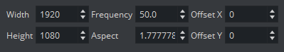
Width: Sets the width in pixels.
Height: Sets the height in pixels.
Frame: Sets the refresh rate/frequency per frame in hertz (Hz).
Aspect: Sets the aspect ratio. For example, 1.778:1, which is 16:9 or 1.333:1, which is 4:3. The designer can set other aspect ratios for each scene, as described in the Scene Settings page in the Scene Management section of the Viz Artist User Guide.
Note: Make sure the physical refresh rate of the graphics hardware and the video hardware are configured with compatible settings.
Offset X: Sets the horizontal alignment in pixels, on the screen. Value is calculated from the top left of the screen.
Offset Y: Sets the vertical alignment in pixels, on the screen. Value is calculated from the top left of the screen.
There are three frequency groups/families: 50, 59,94, and 60 Hz. These define the output format and how fast Viz Engine operates. The frequency is the same as frames per second. This also defines the input format that is allowed, so an NTSC SD input cannot produce a PAL SD output, but an HD input with the same frequency as the SD output would work.
Information: NTSC and PAL are not supported by X.Mio5 boards (2110).
Fullscreen and User Defined hide the Video Output Channel, as these output formats do not support any kind of output channel.
Information: The Colorimetry option only appears for selected resolutions (1080P and above).
UHDTV Support
UHDTV resolution is currently supported on Matrox X.mio3 - DSX LE 4 (SDI video boards only) and X.mio5 (recommended).
UHDTV2 resolution is currently supported on X.mio5 X2. Only 50 FPS is currently supported.
Video Output Editor
The Video Output Editor defines the synchronization standard and the output signal phases.
Freerun: Locks Viz Engine to a clock signal on the video board.
Blackburst: Locks Viz Engine to a Blackburst GenLock signal.
Tri-level: Locks Viz Engine to a Tri-Level GenLock signal.
Auto: Auto detects the genlock signal and locks to it.
Digital Input 1 and 2: Locks Viz Engine to the signal on Input 1 or 2.
PTP: Uses a Precision Time Protocol source for synchronizing. Mainly used in IP networks.
H-Phase and V-Phase: Shifts the output signal with respect to the sync signal.
Note: The Auto option is only available on Matrox boards. On Matrox boards the h- and v-phase settings, are updated automatically with default values based on the output resolution (Except IP-based cards). Measuring the exact h- and v-phase is still required for each setup.
Make the V- and H-Phase Values Coincide
Set the V-phase value.
The V-granularity is taken from the genlock.
The V-delay is calculated from V-phase * V-granularity.
The genlock is set with this V-delay.
Set the H-phase value. Note that there is a distinction between whether the H-phase is a positive or a negative value.
If the H-phase > 0:
The genlock H-delay is set to
0.The H-granularity is taken from the video out channel.
The H-delay is calculated from H-phase * H-granularity.
The fill and key channels are set with this H-delay.
If the H-phase <=0:
The fill and key channel H-delay is set to
0.The H-granularity is taken from the genlock.
The H-delay is calculated from - H-phase * H-granularity.
The genlock is set with this H-delay.
Note: The granularity and possible min/max values are printed to the Viz Artist/Engine console during startup.
It should be taken into account that when the genlock video format is different from the fill/key video format, the value of the V-delay matches the genlock lines and not the video output lines. The same applies to negative H-phase values.
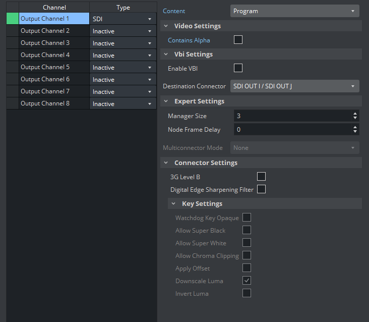
Video Output Channel
In the Video Output Channel panel, you select which Viz Artist/Viz Engine Output is mapped to the Matrox connector. The Video Output Channel panel shows the mapped Viz output channel and its editable parameters. The configuration has the same logic and looks familiar to the Video Input section of the configuration menu (see Video Input: Live Input). This panel is not displayed if Matrox hardware is not used.
Important: If the configuration is done for a Dual Channel UHD setup using SMPTE ST 2110, the second Viz Engine needs to use the second SFP pair for output.
See Explicit Usage of the Second SFP Pair on Matrox X.mio5 Q25 for more information.
To enable an Output Channel, select the row and choose the type of channel. Currently, only SDI type is possible. After that, the content of the channel should be chosen. On single channel configurations, Output Channel 1 has Program as content, and Output Channel 2 has Preview as content. On dual Channel configurations, the first channel uses Output Channel 1 and has Program as content using the first Matrox output connector, and the second channel is the same, except it uses the second Matrox output connector.
The possible content values are:
Unused: Does not map this Matrox channel for output.
Program: Maps the Program output to the selected video output of the Matrox card.
Still Preview: Maps the Preview output to the selected video output of the Matrox card.
Information: It is possible to have up to two programs. The additional program shares the same channel as the still preview, so it is not possible to have two programs and one still preview, for example. It is either two programs or one program and one preview.
Clean: Outputs video without overlay graphics. Clean mode enables and activates a second output feed. This feed consists of DVE video content without any graphics and video textures: only live video, clip video, IP input, streaming input. This stream also includes a separate audio mix corresponding to the video only, excluding stage audio such as audio clips, plug-in audio or text-to-speech, from the clean feed audio mix. If Watchdog functionality is required, VideoOut A must be mapped to Clean, and VideoOut B to Program. The Clean mode requires Matrox X.mio3, X.mio3 IP, X.mio5, or X.mio5 IP (Watchdog functionality is not supported on X.mio5 and X.mio5 IP).
Matte Scene: Used for virtual studios, the effective matte scene.
KeyerAuxChannel: Shows the key preview to adjust the Chroma Keyer.
Downscaled Preview: Outputs a downscaled to HD version of the Program output. This channel is only initialized if the Program output is configured to UHD. It has the same video content of Program, but is downscaled to HD. Otherwise, this channel is ignored by Viz Engine.
GFX1: Outputs whatever is rendered in the chosen GFX channel. The channel can be chosen in the configuration panel when content GFX1 is chosen as content.
GFX2: This is the same as GFX1, to be able to output two different GFX channels.
Note: GFX1 and GFX2 only work when the main scene is VER, but the nested scene can be VER or Classic.
Note: A clean feed increases the video In → Out delay, by one frame.
Note: All additional output content (Matte Scene, KeyerAuxChannel, etc) always requires at least one program to be configured.
Note: It is only possible to have one of each output content. The exception is the Program output content, which you can have a maximum of two, as long as StillPreview is not already used.
Fill Properties
Digital Edge Sharpening Filter: Applies an edge sharpening filter to digital output video. Default mode is
Inactive. SD configurations only.
Key Properties
Contains Alpha: Defines if this output channel provides key information on the associated key output connector.
Watchdog Key Opaque: Specifies if the output key must be opaque or transparent when the watchdog unit activates. Default mode is Inactive.
Allow Super Black: Allows the luminance of the output signal to fall below the nominal SMPTE pixel values (7.5 IRE units) when enabled. Default mode is Inactive.
Allow Super White: Allows the luminance of the output signal to exceed the nominal SMPTE pixel values (100 IRE units) when enabled. Default mode is Inactive.
Allow Chroma Clipping: Determines whether to clip over-saturated chroma levels in the active portion of the output video signal. Default mode is Inactive.
Apply Offset: Applies an offset to the luminance values such that the inverted result still falls within the 16-235 range. Default mode is Inactive.
Downscale Luma: Compresses the luminance range of the output key signal from 0-255 to 16-235. Default mode is Active.
Invert Luma: Inverts the luminance part of the output key signal (inverts the key). Default mode is Inactive.
Multiconnector Mode
Defines which multiconnector mode to use for 3G / 12G SDI channels. This setting is only available for Series 5 Matrox SDI cards (for example, X.mio5 12G SDI) when configured to UHD.
None: 12G single connector mode.
2SI: Quad-Link 2 sample interleave.
Square Division: Quad-Link Square division.
Important: Multiconnector mode is only enabled for UHD resolutions and when at least four connectors are available.
If fewer than four connectors would be free for SQD or 2SI, this option is greyed-out and the connectors automatically run at their maximum bandwidth.
Manager, Repeat and 3G Properties
Manager Size (frames): Sets the number of frames available in the on-board memory for output. A too high value may cause memory problems on the Matrox board. Default value is
3.3G Level B: Activates
Level Bfor 3G mode in 1080p 50/60/60M (default mode isLevel A).
VBI Properties
Use this switch to enable or disable VBI (Vertical Blanking Interval) in the output.
See Also