This section details Topology configuration, which includes Tracking Systems, Rigs and Services.

At any time, view the properties of each configuration in the Configuration Panel.
The Topology configuration should be done in this order:
Configure a Tracking System.
Configure a Rig.
Configure a Service.
Configure a Tracking System
To Add and Configure a Tracking System
Click
 .
.Type a Name for the configuration.
Select which protocol to use to receive data from the tracking system:
Note: If changing the protocol of an already configured tracking system, the default configuration parameters for the new protocol are read by the system.
Select a connection type. Depending on the tracking system select the connection type:
Serial: If serial is selected, also select a Comport (in the Comport box, all available comports are shown). If the default baud rate is not used, enter the correct one in the baudrate field. Also set the parity, stop bits and data bits according to the values provided by the manufacturer.
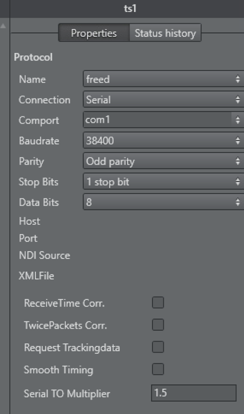
The Serial Timeout Multiplier should only changed in values between1.1and2.0and needs to be adjusted only when receive problems occur.TCP/IP: Type in the Host IP to use (it is possible to enter the port number as well).
UDP: Type in a Port number to use.
NDI: please see: Embedded NDI Tracking Data.
Options available for all tracking systems:
ReceiveTime Corr: Ignores the receive time of the package and sets it to the last sync time. This makes the interpolation smother, assuming that the tracking data sample rate is stable. Sometimes the tracking data transport can be unstable, for example, when serial data is converted to fiber and back to serial. In this case, the tracking packages are coming irregularly.
TwicePackets Corr: Shifts double packets to the correct receive time. As a special case of the ReceiveTime Corr., it can also happen that two tracking packets arrive at the same time. This is often the case when old USB converters are used.
Request Trackingdata: Forces Tracking Hub to send the trigger to the tracking system. There are still some old tracking systems in the field which demand a trigger to send the data to Tracking Hub. Such systems are Thoma or old Vinten heads.
Smooth Timing: Forces Tracking Hub to distribute the income time of all received packages evenly. Use when Receive Time Corr. and TwicePackets Corr. do not have the desired effect.
Serial TO Multiplier: Determines the timeout when Tracking Hub reports missing tracking data is defined by the frequency of the studio sync (for example, for PAL the timeout is 20 milliseconds). When the packets are coming irregularly, Tracking Hub would continuously show an orange status. This timeout multiplier can improve the result by increasing this timeout interval.
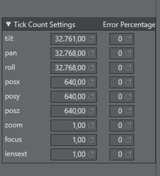
Tick Count Settings: Most encoder based systems do not send angles or position in centimeter to Tracking Hub. They send an encoder based tick count, which must then be converted to angles and positions. Usually, the divisor of the tick count is defined by the protocol. This default values are predefined in Tracking Hub. In rare cases it can happen that the tick count differs from the default values. When the tracker is disconnected this default values can be adjusted.
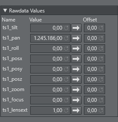
Rawdata Values: The Rawdata Values show the actual incoming ticks per axis. It is also possible to add an offset to the tick count. This can be useful during lens calibration of when setting up a crane. This panel is only visible when the tracker is connected.
Post Settings: Please see: Post System.
Error Percentage: Sometimes it can happen, especially when using old tracking systems, that an encoder get damaged. This usually results in one frame short random values sent to the Tracking Hub. The error percentage is the limit when Tracking Hub filters out unplausible values. The filter is activated when the actual value differs more than the error percentage from the last value.
Caution: This is an emergency solution. If such errors occur, the tracking system must be repaired as soon as possible.
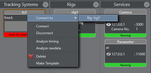
Right-click on the Tracking Systems box and select Connect (connect to the tracking system).
The Tracking Hub now connects to the selected Tracking System. Observe the colors on the bottom of the symbol:Green: Connection is done and data receiving in time.
Orange: If the color becomes orange, after a few seconds, connection is done and data receiving, but not in time.
Red: If the color becomes red, possible connection failure or data is not received.
Go to Configure a Rig.
Configure a Rig
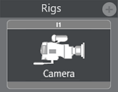
Click
.Select from the list:
Add simple camera:
Right-click the Tracking System and select Connect to > Rig (Lattice).

Set or change tracking parameters as required. When finished Click OK.
Go to Configure a Service.
Configure a Service

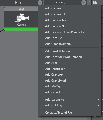
Click
.
Select a Service:
Add camera service
Add object service
Click on the service icon in the Services panel.
Configure the service in the Properties panel. When the service is added, one rig and one camera field are available. Pressing the + button add a rig/camera combination. It is possible to send any number of rigs to one Engine.
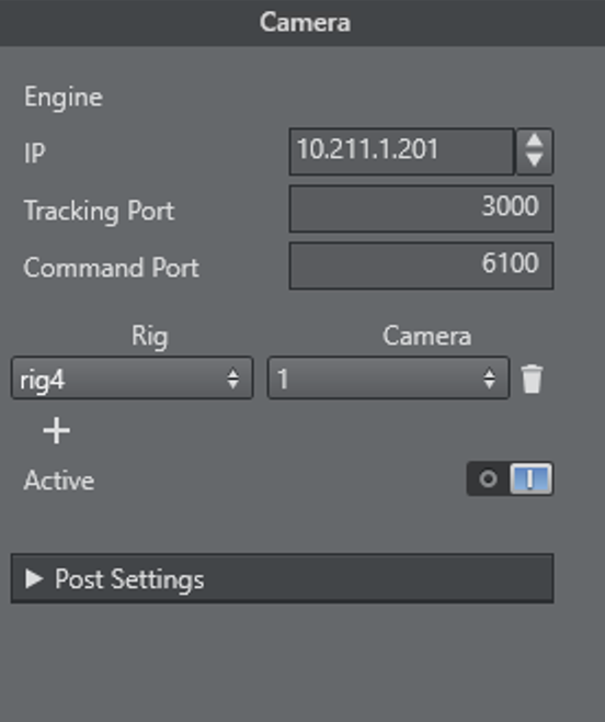
Rig: Type the name of the rig whose data should send to an Engine.
IP: IP address of the Viz Engine, which is to receive the tracking data.
Port: Port number for this connection (same port as configured in the Viz Engine configuration).
Cam.Number: Same as Viz Engine is expecting.
Mode: Not in use (default =
0).Active: When checked the service is active, unchecked no data is sent to the Viz Engine.
Click Start in the Configure the Studio.
Click Save in the Configure the Studio.
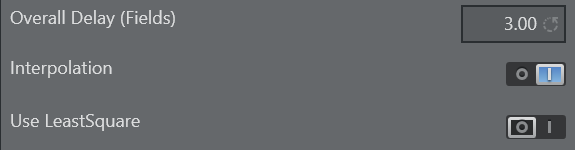
Set a Delay
To match tracking data with the Engine rendering, set a delay (in fields). The delay can be set in fractions of fields and individual for every parameter.

A delay can be set for each parameter individually or overall for the whole camera rig node. The parameter delay is added to the the overall delay.
Set an Offset
An offset (cm) can be added to a tracking parameter value, when passed to a rig, to correct positional rotation of a camera and, or an object

Values are set, if the field has lost its focus.
Set Center Shifts
In case a drift of graphics can be seen while zooming the camera, the center shifts might need adjustment (image above shows example values).

A guide on how to properly adjust center shifts can be found in chapter Tracking Hub Structural Design.
Analyze Time
Analyze Time is a visual representation of the tracking.
To Analyze Tracking System Time
Right-click on the Tracking System that is to be analyzed and select Analyze Timing.
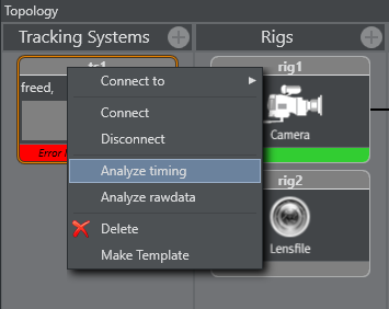
This adds a new element to the Services panel, called TrackingTiming.Click on the TrackingTiming Service element. In the Properties panel, make sure that:
The IP of the local PC is inserted, and
The service is set to Active.
To Analyze a Service Time
Right-click on the Service System that is to be analyzed and select Analyze Timing.
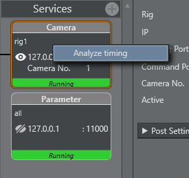
This adds a new element to the Services panel, called TrackingTiming.Click on the TrackingTiming Service element. In the Properties panel, make sure that:
The IP of the local PC is inserted, and
The service is set to Active.
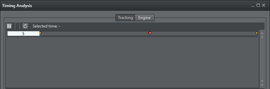
To View Timing Information
In the Configuration Panel, click the View Timing Analysis button
 . In a Timing panel with a correct data stream:
Purple line: Shows the time when the Tracking Hub has inserted a data package from the tracking system into the data pool.
Green line: Shows the time when the communication part of the Tracking Hub starts to read from the data pool.
Red Dot: Indicates data sent to a Viz Engine has stopped.
Upper Section
In the upper section, the first line is the timing of live tracking data.
These timestamps are shown:
Sync:
Start RX: Start time, when data is received from the tracking system.
End RX: End time, when data stops from the tracking system.
Start Ins: Start time, when Tracking Hub inserts received data into the parameter pool.
End Ins: End time, when Tracking Hub has finalized inserting data.
Orange Dot: Sync Timestamp
Blue: The time between Start RX and End RX
Note: The time between Start RX and End RX can be very short and thus almost invisible if network communication is in use.
Purple Line: The time between Start Ins and End Ins
Line 2: Shows when the live tracking data is processed and sent to the Viz Engine.
Start Calc: The start time. When tracking data is calculated and prepared for a Viz Engine, this time is defined from send delay. After this delay has passed the Tracking Hub starts with this procedure for calculation and sending data.
End Calc: The end time. When tracking data preparation is finished.
End Send: Time when data has been send to the Viz Engine.
Green Line: Time between Start Calc and End Calc.
Red Dot: End Send Timestamp
Lower Section
The lower part shows the last ten second history of the timing. Three timestamps are shown.

Note: Only three timestamps are shown to make the recognition of the timing behavior easier.
End Ins: As time, when receiving is finished, shown in purple (1).
Start Calc: When data processing starts, shown in green (2).
End Send: When Tracking Hub work is finished for this field, shown in red (3).
To get the optimal timing, the Start Calc time must be later than the End Ins time, for every field. To achieve this, the send delay has to be adjusted correctly. The white line shows the delay. This line should be the absolute border between End Ins (purple line) and Start Calc (green line). To change the delay, use drag and drop to move the white line. If the delay can not be adjusted correctly, this can be for several reasons, for example, tracking data is received too late.
Note: This is not too bad, but keep in mind, that this result is in a tracking delay of one field.
This doesn't matter so much, because in normal production you need more the one field tracking delay.
Lens Range Calibration
This section details how to calibrate the Lens Range.
First, collect the minimum and maximum Values of Zoom and Focus:
In the Tracking System properties panel, click the Calibration button:

Go to the broadcast camera and move Zoom and Focus to their upper and back to their lower limits, at least two times. Observe that the system receives the full set of data:

To check if the calculation is correct, the corresponding Min/Max values, of the Lens encoder, are shown in the Zoom and Focus fields.

Re-using Lens Ranges from Older Version Lens Files
The lens range in Tracking Hub is from 0 to 1. For setups used with software preceding the Tracking Hub, such as Viz IO, the lens files may have used lens ranges specified slightly differently, such as from 0.01 to 0.99. The Tracking Hub is capable of adapting to such a lens range. To achieve this, the lenserange parameter in the studio configuration file needs to be entered manually.
Warning: Editing the configuration manually can lead to software malfunction, and should only be done by qualified professionals.
Modify a Rig
If a Tracking System parameter does not equal a Viz Engine parameter, a Viz Engine parameter can be modified to adapt to the Tracking System parameter.
To modify a Rig
Right-click on a Tracking System. Select Connect to a rig.
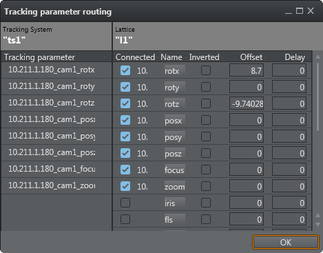
The Tracking parameter routing window opens.

The Tracking System panel shows all the parameters that can be tracked.
The Rig panel shows the Rig connections.
If a Tracking System parameter does not equal a Viz Engine parameter, a Viz Engine parameter can be modified to adapt to the Tracking System parameter. Click on a Viz Engine parameter and drag to its new position, as required. If a red cross shows, after a parameter has been modified, it means that the connection is still valid, but the connection is now a cross-over connection and not a straight one.

In the Offset column, define an offset to each parameter. The values are given in centimeters or degrees (value with dot). The values are stored when the field loses focus.
In the Delay column, enter how many fields sending of the parameter should be delayed.
Click on a box under Connected to connect a parameter through the rig.
Click OK.
No Tracking Parameters
If the Tracking parameter panel empty, there are no tracking parameters delivered from the tracking system.

Check what the icon of the tracking system shows (disconnected or connected, color, etc.).
Check all connectors until the required connections show in the Tracking Parameters panel.
Go to To Modify a Rig.