Viz Arc lets you work with both outdoor and indoor Augmented Reality events. You can search for a specific place in maps and set up your outdoor set or import an AutoCad project and set up the entire elements environment in the scenography.
Note: Viz Arc uses the metric system.
This section covers the following topics:
Map
Map items can retrieve map data from Bing.
Bing Map |
|---|
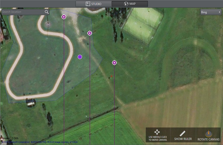 |
Map is used to set up an external environment. You can search for a place in the search bar and place elements directly info the map area. Map uses XYZ positions OR geolocation and transforms them into Viz Units. The map menu lets you:
Zoom in/out with the mouse wheel.
Move the map with the center mouse button.
Left-click on an element to move it.
Right-click on an element to remove it.
Right-click on a map:
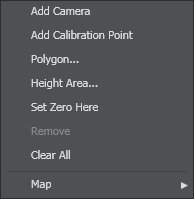
Set up a Height Area to intercept the height of the object
Clear All elements in map (except for the Zero Point)
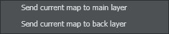
By selecting a Map item, you can choose to send your current map to the main layer or back layer:
Studio
It's possible to import an AutoCAD project (.dxf) and set up cameras and objects directly into your custom studio using STUDIO.
Indoor Map |
|---|
 |
Studio is used to set up an internal environment. You can import your Studio map project using the Browse icon ![]() and place elements directly into the plan area. Studio uses Viz Units only.
and place elements directly into the plan area. Studio uses Viz Units only.
Working with Virtual Studio
This section covers how to set up virtual studio and augmented reality elements in relation to your physical environment.
To Position an AR Element
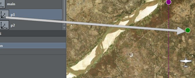 | Drag and drop the desired container’s plugin (only position or transformation control channel) into the map area. |
The green icon appears on the map. | |
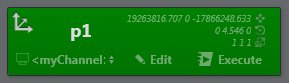 | The same elements action that was just created can also be found in the action pane in the main window. |
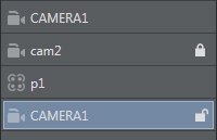
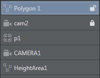
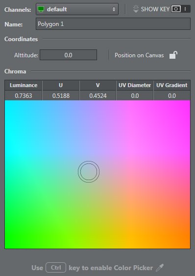
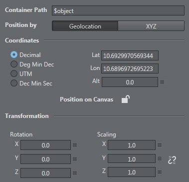 | Selecting the icon or element in the list makes the corresponding config section appear on the right side of the SET window. |
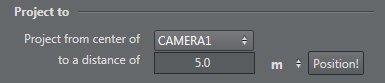 | This menu lets you position graphics along the camera center at a given distance. |
 | This icon lets you lock or unlock an element position on the map canvas. |
To Add a Calibration Point
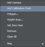 | Right-click on the map OR in the studio area and select Add Calibration Point in the context menu. |
The target icon appears on the map. | |
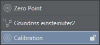 | The item is also added to the element list on the right of the map/studio area. |
 | Selecting an icon or element in the list makes the corresponding config section appear on the right side of the SET window. |
| It’s possible to lock or unlock a camera position on the map canvas using this command. |
To Set up a Camera
 | Right-click on the map OR in the studio area and select Add Camera in the context menu. |
The camera icon appears on the map. | |
 | The item is also added to the element list on the right of the map/studio area. |
 | Selecting an icon or element in the list makes the corresponding config section appear on the right side of the SET window. |
| It’s possible to lock or unlock a camera position on the map canvas using this command. |
To Draw a Polygon
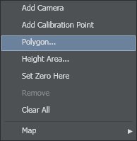 | Right-click on the map OR in the studio area and select Polygon… in the context menu. |
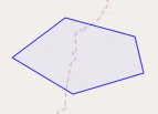 | The cursor transforms into a pen Mark as many vertices as you need. |
 | The item is also added to the element list on the right of the map/studio area. |
 | Selecting an icon or element in the list makes the corresponding config section appear on the right side of the SET window. |
| It’s possible to lock or unlock a camera position on the map canvas using this command. |
To Set up a Height Area
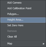 | Right-click on the map OR in the studio area and select Height Area… in the context menu. |
 | Click once to set a point and click again to set the height. This icon appears on the map. |
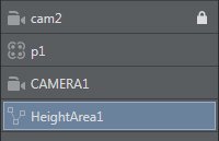 | The item is also added to the element list on the right of the map/studio area. |
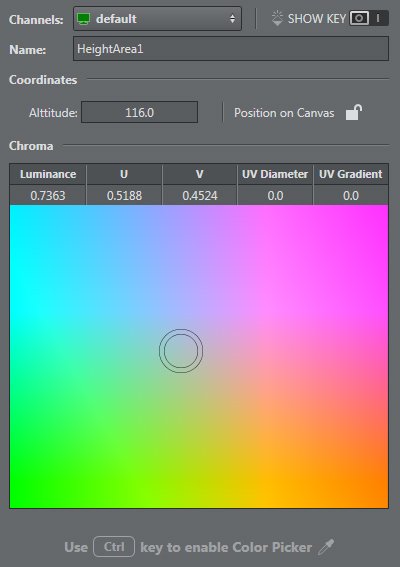 | Selecting an icon or element in the list makes the corresponding config section appear on the right side of the SET window. |
| It’s also possible to lock or unlock the height area position on the map canvas. |
To Set a Zero Point
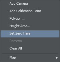 | Right-click on the map OR in the studio area and select Set Zero Here in the context menu. |
This icon appears on the map. | |
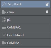 | The item is also added to the element list on the right of the map/studio area. |
 | Selecting an icon or element in the list makes the corresponding config section appear on the right side of the SET window. |
| It’s also possible to lock or unlock a zero point position on the map canvas. |
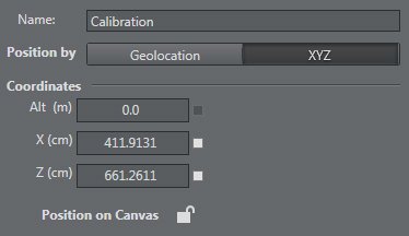
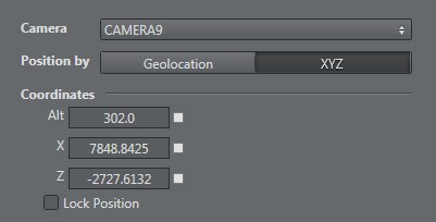
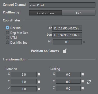
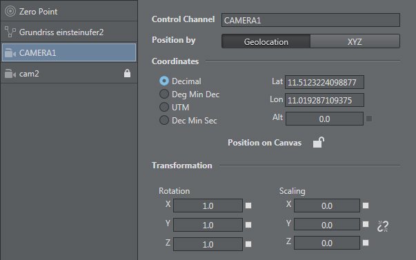
Once an element (like a camera) has been added, it's possible to edit the parameters:
Position – choose between
geolocalization: latitude, longitude, altitude, and type: Decimal, Deg Min Dec, UTM , Dec Min Sec
XYZ
Rotation
Scaling
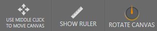
You can toggle show ruler to make small adjustments to element positions on the map. Rotate canvas by holding down the left cursor button to the desired map position.
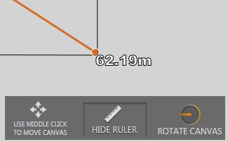
Tip: The Ruler tool is useful since it allows you to measure the distances on your area in Viz Arc in real time.
Note: It's possible to delete all elements in a map except the Zero Point.
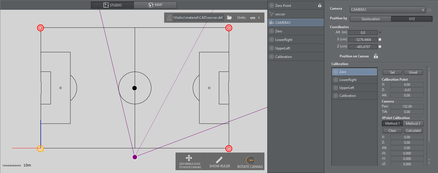
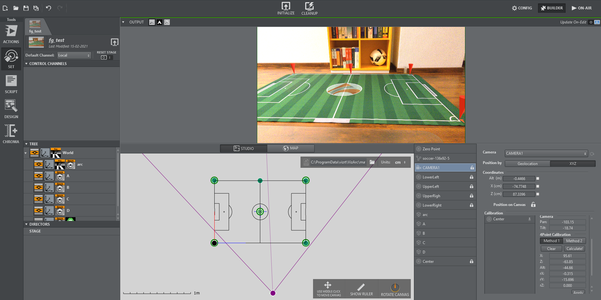
4 Point Calibration
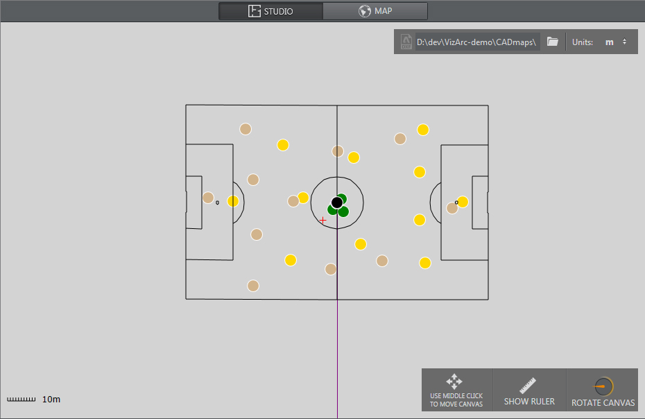
4 Point Calibration can be used to calculate the position and orientation of a (typically mechanically) tracked camera. Using this type of calibration requires knowledge of at least four physical points in the domain (for example, the corners of a soccer pitch or well-known points on a horse race track).
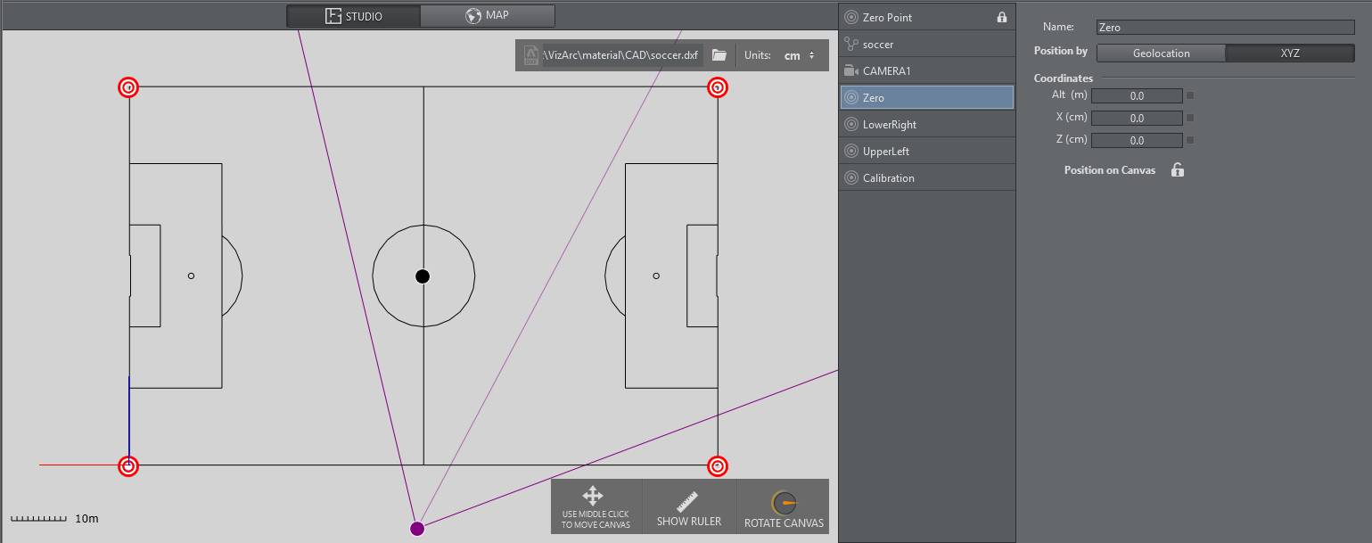
Map View showing a soccer pitch and 4 calibration points.
Prerequisites
The calibration points must all be on the XZ plane (same height).
The camera must be on a fixed position and can't be moved in space.
At least four points need to be measured/known on the tracking domain.
The points must define a surface and not just a one dimensional line.
Make sure the tracking hub sends the tracking information to Viz Arc and make sure it includes the camera lens rig containing a valid calibration.
Note: Do NOT use a parent transformation rig on top for 4 Point calibration. The translation and rotation are handled inside the root node of the Viz Artist scene.
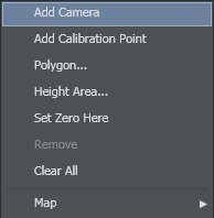
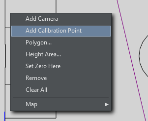
Adding Calibration Points
Add calibration points from the map's context menu:
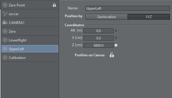
Select the calibration point you just added and move it on the map, or enter its coordinates manually:
Once all calibration points have been added and positioned, the actual calibration process may start.
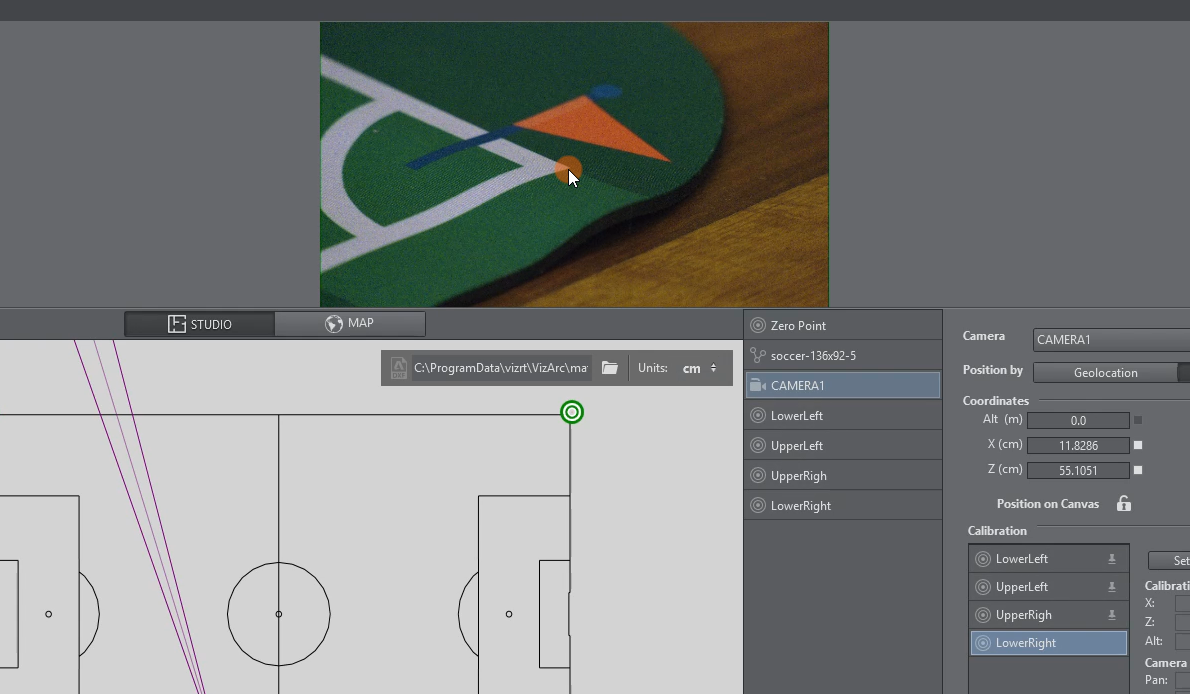
Calibration
Select the camera to be calibrated.
On the camera user interface select the marker towards which you want to point the camera. The calibration point is colored yellow on the map canvas.
The physical camera should now fully zoom into the marker and try to center it as best as possible.
Once the marker is centered, click the Set button. If your preview has been set up so that the camera is visible and you have a valid lens calibration, you can also click the position in the view instead of using the Set button.
Continue this procedure for all or at least 4 calibration points.
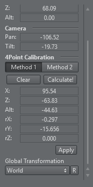
Applying Calibration
Once at least four points have been set, click the Calculate! button to calculate the presumed position and orientation of the camera. You can choose between Method 1 and Method 2, hit Calculate! after switching algorithm. Generally, Method 2 is more accurate but needs more and more accurate calibration points. Try both and pick the one that gives you better visual results.
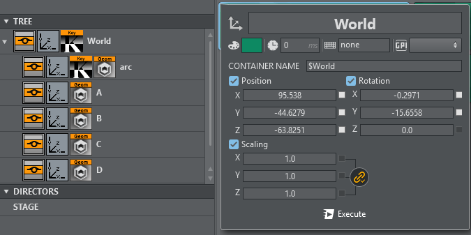
Under the Global Transformation dropdown, select the transformation action holding the world transformation of the main scene (typically the root node of the AR/VR scene).
Click Apply to apply the calculated transformation and rotation.
Use the R button to refresh the list of available transformation actions.
Typically the transformation to be used is the root node of the scene.
Once calibrated you should be able to position AR graphics on your pitch.