Viz Engine
Version 3.10 | Published April 03, 2018 ©
Matrox
In the Matrox section assign Matrox Input and Output channels to Viz Engine Input and Output channels.
The GUI shows a drop down menu for the configurable parameters. The parameters available is dependent on the installed hardware.
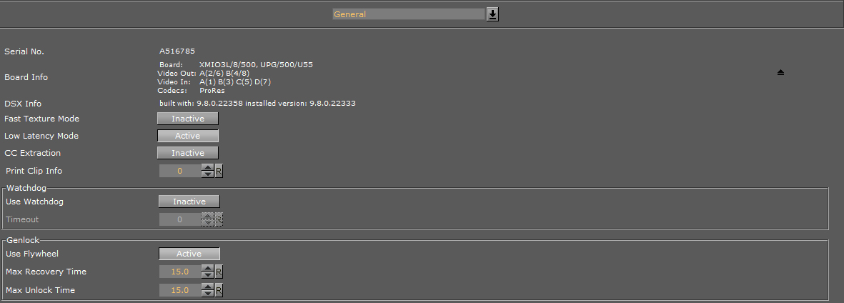
General Properties
The General properties panel shows information about the installed hardware.
-
Serial No.: Shows the serial number of the installed Matrox board.
-
Board Info: Shows the model and type of the Matrox board.
-
DSX Info: Shows the software version and driver version.
-
Fast Texture Mode: Activate to shorten the ’in out’ delay in Texture Mode to a minimum.
Note: If Fast Texture Mode is set to Active, DVE will not work (see Video Clip Playout Considerations and Video Playout in the Viz Artist User Guide).
-
Low Latency Mode: Enables Low Latency Mode required for Viz Opus with the Matrox X.mio3. Applies only to hardware configurations using the Matrox X.mio3 video board. Disabled by default.
Note: Low Latency Mode is always enabled for configurations using the Matrox DSX LE 4 video board, and the setting cannot be changed for this card.
-
CC Extraction: Enable or disable the closed captioning extraction for Matrox X.mio3 and X.mio2+.
-
Print Clip Info: When activated, this setting enables printing of clip information to the console. However, such information may cause the render loop to stall. Default mode is Inactive.
-
Watchdog: A timer that allows a system to continue video pass-through during an application crash or system failure (see also Watchdog (Matrox X.mio Series) and Video Board):
-
Use Watchdog: When set to Active enables the Matrox X.mio watchdog feature. It passes the input signal to the output when the Viz Engine is unresponsive. Default mode is Inactive. When set to Active, video out set to off, will activate the after a given timeout (see Timeout) (see also ).
-
Timeout: Set the time, in milliseconds, until the watchdog takes over control. This value should not be smaller than the time of two fields/frames. Default value is 999 milliseconds.
Note:Use Watchdog and Timeout can also be set and changed in Video Board.
-
-
Genlock:
-
Use Flywheel: When activated, the Matrox board adopts a tracking mode if the genlock signal is interrupted or lost that maintains the signal frequency until the source genlock signal is regained. Default mode is Active.
-
Max Recovery Time: Represents the time in milliseconds (ms) provided to the flywheel to attempt to regain the genlock before an abrupt jump to the locked state is performed. Default value is 15.
-
Max Unclock Time: Represents the time in milliseconds (ms) provided to the flywheel to remain in the unlocked state before switching to the free running state. Default value is 15.
-
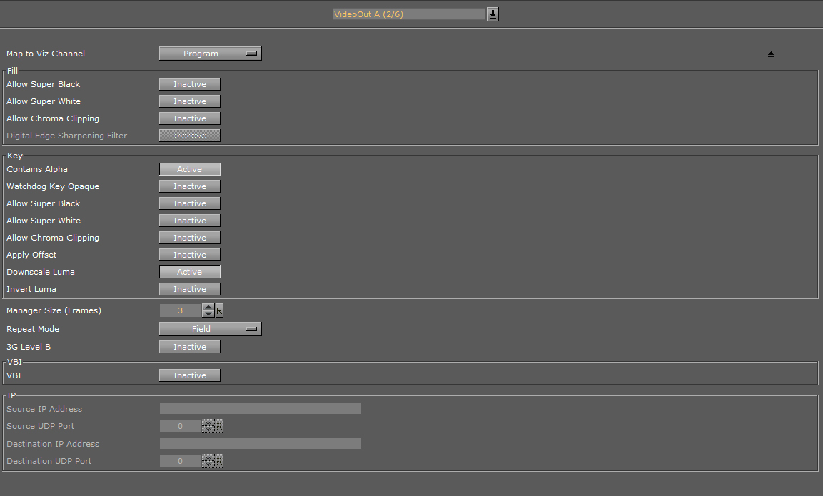
VideoOut Properties
In the VideoOut panel select which Viz Artist/Engine Output is mapped to the selected Matrox Output. The VideoOut panel shows the mapped Viz output channel and its editable parameters.
Map to Viz Channel
-
Map to VizChannel: Select which video out channel is mapped to the selected Matrox video out channel. Select an Output channel from the drop-down menu. Only channels not already in use are shown. On single channel configurations, VideoOut A is usually mapped to Program, and VideoOut B to Preview. On Dual Channel configurations, the first channel maps VideoOut A to Program, and the second channel maps VideoOut B to Program.
-
Unused: Do not map this Matrox channel for output.
-
Program: Map the Program output to the selected video output of the Matrox card.
-
Preview: Map the Preview output to the selected video output of the Matrox card.
-
Clean: Output video without overlay graphics. Clean mode enables and activates a second output feed. This feed consists of DVE video content without any graphics and video textures: only live video, clip video, IP input, streaming input. This stream also includes a separate audio mix corresponding to the video only, excluding stage audio such as audio clips, plug-in audio, text-to-speech, etc., from the clean feed audio mix. If Watchdog functionality is required, VideoOut A must be mapped to Clean, and VideoOut B to Program. Requires Matrox X.mio3, X.mio3 IP, or DSX LE4.
-
Fill Properties
-
Allow Super Black: Determines whether or not to clip an output video signal that is under 7.5 IRE units. Default mode is Inactive.
-
Allow Super White: Determines whether or not to clip an output video signal that is over 100 IRE units. Default mode is Inactive.
The colorimetry tables for SD (ITUR-BT 601) and HD (ITUR-BT 709) define a color conversion from YUV with the range of 16-235 to RGB with the range of 0-255. Values above 235 are Super White and values below 16 are Super Black. As Super White and Super Black pixels are outside the range of 1-byte RGB, these pixels will be clamped to the normal 16-235 YUV range when used in a texture. -
Allow Chroma Clipping: Determines whether or not to clip over-saturated chroma levels in the active portion of the output video signal. Default mode is Inactive.
-
Digital Edge Sharpening Filter: Applies an edge sharpening filter to digital output video. Default mode is Inactive. SD configurations only.
Key Properties
-
Watchdog Key Opaque: Specifies if the output key must be opaque or transparent when the watchdog unit activates. Default mode is Inactive.
-
Allow Super Black: Determines whether or not to clip an output video signal that is under 7.5 IRE units. Default mode is Inactive.
-
Allow Super White: Determines whether or not to clip an output video signal that is over 100 IRE units. Default mode is Inactive.
Note: Please see the description about allowing Super White and Super Black in the Fill Properties section above.
-
Allow Chroma Clipping: Determines whether or not to clip over-saturated chroma levels in the active portion of the output video signal. Default mode is Inactive.
-
Apply Offset: Applies an offset to the luminance values such that the inverted result still falls within the 16-235 range. Default mode is Inactive.
-
Downscale Luma: Compresses the luminance range of the output key signal from 0-255 to 16-235. Default mode is Active.
-
Invert Luma: Inverts the luminance part of the output key signal (inverts the key). Default mode is Inactive.
Manager, Repeat and 3G Properties
-
Manager Size (frames): Sets the number of frames available in the on-board memory for output. A too high value may cause memory problems on the Matrox board. Default value is 3.
-
Repeat Mode: Defines the way the output should be repeated if Viz Engine is stalled and does not update the output. Default mode is Field. Available modes are:
-
None: Does not repeat. Output goes black.
-
Field: Repeats the last played field.
-
Frame: Repeats the last played frame.
-
-
3G Level B: Activates Level B for 3G mode in 1080p 50/60/60M (default mode is Level A).
VBI Properties
Use this switch to enable or disable VBI (Vertical Blanking Interval) in the output:
-
Active: Enable VBI output
-
Inactive: Disable VBI output
IP Properties
These configuration settings are specific to the Matrox X.mio3 IP video board, and will be inactive if such a board is not installed.
-
Source IP Address: Sets the IP address of the particular SFP being configured.
-
Source UDP Port: Sets the UDP port of the particular SFP being configured.
-
Destination IP Address: Sets the destination IP address. If sending to another Viz Engine with a Matrox X.mio3 IP board, or the other SFP on the local machine, this must be a multicast address in the IP Multicast address range, such as 224.10.10.31 or 239.10.10.51.
-
Destination UDP Port: Sets the destination UDP port.
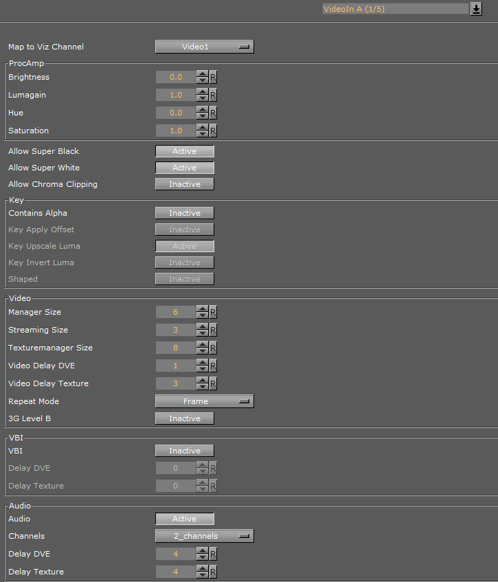
VideoIn Properties
The VideoIn tab shows the mapped Viz Artist channel and every setting of the input channel which can be controlled.
Map to Viz Channel
-
Set which video in channel is mapped onto this Matrox video in channel. The drop-down gives a choice between the available channels. Only the channels not already taken are shown.
-
Unused: Do not use this Matrox channel for video input
-
Video <1 to 8>: Captured input is available in Video1.
Note: On a single channel configuration VideoIn A is usually mapped to Video1 and VideoIn B to Video2 and so on whereas for a Dual Channel configuration usually the first channel maps VideoIn A to Video1 and the second channel maps VideoIn B to Video1. In this case both the first and the second channel have one video input configured, namely Video1.
Note: When running a machine with two graphics cards (i.e. a Dual Channel or Trio Box CG setup) video inputs are hardware resources on the Matrox board, that cannot be shared. If one input for both Viz Engine instances is required, split the signal and apply it to 2 video input connectors.
-
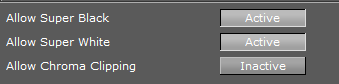
Allow Properties
-
Allow Super Black: Determines whether or not to clip an input video signal that is under 7.5 IRE units. Default mode is Active.
-
Allow Super White: Determines whether or not to clip an input video signal that is over 100 IRE units. Default mode is Active.
-
Allow Chroma Clipping: Determines whether or not to clip over-saturated chroma levels in the active portion of the input video signal. Default mode is Inactive.
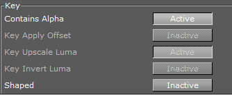
Key Properties
-
Contains Alpha: Enables/Disables use of alpha component.
Note: This switch is only enabled on input channels where capture with alpha is supported.
-
Key Apply Offset: Applies an offset to the luminance values so that the inverted result still falls within the 16-235 range.
-
Key Upscale Luma: Expands the luminance range of the input key signal from 16-235 to 0-255.
-
Key Invert Luma: Inverts the luminance part of the key signal (inverts the key).
-
Shaped: Enables/Disables capture in shaped format.
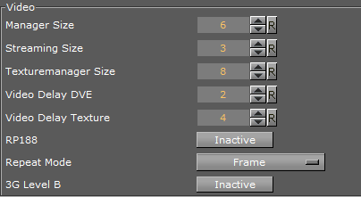
Video Properties
-
Manager Size: Sets the number of frames available in the on-board memory for capturing. This value is influenced by the input delays specified in the parameters below and will automatically be adjusted if it is too low. A too high value may cause memory problems on the Matrox board. Default value is 6.
-
Streaming Size: Not in use.
-
Texturemanager Size: Defines the size of the texture buffer in frames. Default value is 8.
-
Video Delay DVE: Sets the number of frames the live input should be delayed before it can be used as a DVE layer. Default value is 0 (Off).
-
Video Delay Texture: Sets the number of frames the live input should be delayed before it can be used as a texture in the scene (default value is 4 (this is the minimum value, the maximum value is 50).
Note: X.mio2 and DSX.LE3 minimum delay is 4, and the X.mio2 Plus minimum delay is 1. These values are for the hardware and cannot be decreased. If set to below the minimum value in the GUI the engine will reset to the minimum value.
Note: For certain input resolutions these minimum values are not sufficient and need to be increased. The the Viz Engine installation provides configuration templates for each video resolution.
-
RP188 Enable: Enables capturing of SMPTE RP 188 extra information such as LTC and VITC. Default is Inactive.
-
Repeat Mode: Determines the behavior of the video input in case of capture drops. Options are:
-
None: Does not repeat. Input goes black.
-
Field: Repeats the last field.
-
Frame: Repeats the last frame.
-
-
3G Level B: Activates Level B for 3G mode in 1080p 50/60/60M (default mode is Level A).
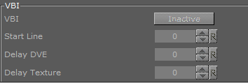
VBI Properties
-
Enable: When set to Active this setting will enable VBI for this channel. Default is Inactive.
Note: If the input resolution is different from the output resolution it is impossible to activate since can only be inserted if the resolutions are the same.
-
Start Line: Defines at which line on the input the VBI section will start. Default value is 0 (Off). The minimum VBI values are (as for VideoOut):
-
NTSC: 7
-
PAL: 6
-
720p: 7
-
1080i: 6
-
-
Delay DVE: Sets the number of frames the VBI should be delayed before the clip can be used in DVE mode (Default is 0 (Off)).
-
Delay Texture: Sets the number of frames the VBI should be delayed before the clip can be used in texture mode. Default is 0 (Off).
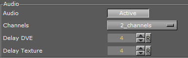
Audio Properties
-
Audio: When set to Active this setting enables audio capturing on this channel. Default mode is Active.
-
Channels: Sets the number of audio channels to capture (see also Audio in Viz).
Default number of channels are 2. Available channel options for AES on X.mio are:-
None, 1, 2, and 4.
For AES on X.mio2/X.mio2 Plus and for Embedded the channel options are: -
None, 1, 2, 4, 8, and 16.
-
-
Delay DVE: Sets the number of frames the audio should be delayed in DVE mode before it can be mixed to the output. Default value is 4.
-
Delay Texture: Sets the number of frames the audio should be delayed in texture mode before it can be mixed to the output. Default value is 4.