Router Control
Camera cuts can be controlled from within the Studio Manager by using the Router Control, accessible via the Tools menu. The Router Control can control camera cuts by using presets, or manually. By adding presets for the most commonly used inputs and outputs, this interface allows for quick and easy camera cuts on demand.
When Router Control is in use, an additional configuration file is used. This file is located in %ProgramData%\vizrt\VizTH\Cfg\<Studio config name>, and the file is named XML_TH_RouterCfg.xml.
At any given time, configured connection or preset parameters can be deleted independently from the overall router control configuration by clicking the corresponding trash can icon.
To Add a Router Control Preset
-
Open the Tools menu and select Router Control.
-
In the dialogue window that opens, select a Model and enter a Name for the router, then click Add. The selected model defines the communication protocol which will be used, and is not vendor dependent. The available protocols are:
-
Black Magic
-
Nevion MRP (network)
-
Nevion NCB (serial)
-
-
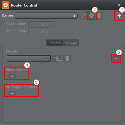
Click the plus icon (
+)in the upper right corner to add a router (1). If a router has been added to the system previously, it can be reused by selecting it from the Router drop-down list. -
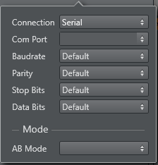
Click the cogwheel icon to configure the connection settings and AB mode for the router (2).
-
Connection: Select the connection protocol. Available options are Serial, UDP and TCP. For serial connections, the Com Port needs to be set in all cases. The other parameters may be left to their default settings, or specified based on the requirements of the specific hardware connected. Please refer to the vendor documentation for connection details.
-
AB Mode: AB mode is used to deal with situations with unreliable routher switching times. When running in AB mode, two SDI cables are connected from the router to the Viz Engine inputs. Upon switching, the router first switches the signal to the unused line. If the signal is valid, the command to switch the input and camera is sent to the engine. This way, the output from Viz Engine will not be interrupted even if the router switching has a slight delay.
-
-
If required, a delay can be added in the Preset Delay or Engine Delay fields.
-
Next, click the plus icon (
+)to the right in the Preset section to add a preset (3). Enter a Name and click Add.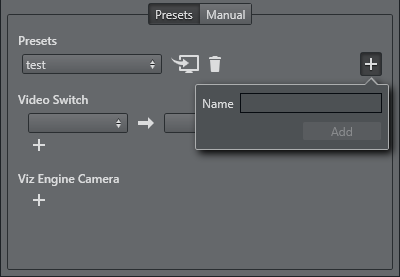
-
In the Video Switch section, select the Input and Output on the router from the left and right drop-down lists, respectively.
-
In the Viz Engine Camera section, select which Engine and camera to switch to.
A router connection with a preset has now been configured, and the Router Control window should look like this:
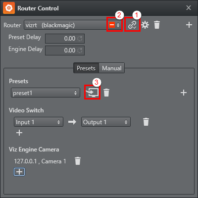
Click the Connect button (1) to connect to the configured router. If there is a connection problem, this will be indicated by a red warning box in the Router drop-down list (2). To issue the take command to the router and Engine, click the Take button (3).